Stepper Motors > Technology > Stepper Motor Loss Technology
Stepper Motor Lower Loss Technology Development
Abstract
The demand for stepper motors that have high efficiency and low losses has been increasing, although it had been previously focused on high torque. The selection of the most suitable grade for and the improvement in fastening of the laminated cores has reduced the losses significantly at their peak when compared to conventional stepper motors. Lowering the losses of the motor has enabled continuous operation that was previously impossible. An expansion of the stepping motor’s usage into applications where another motor has been used for continuous operation and other uses due to the heat generation problem can now be pursued. In addition, these motors are very effective for energy saving. This paper explains the technology used for lowering the iron losses of the stepper motor.
1. Introduction
The stepper motor can control the speed and the position accurately in an open loop control mode. The stepper motor had a disadvantage of large heat generation when rotating at high speed. It has had an advantage in which it can be used easily. The stepper motor has been used mainly to utilize the standstill holding brake force and the torque at low speed. However, recently, another customer demand for being able to operate continuously at high speed has risen thereby shortening the cycle equipment time. The motor loss is greatly reduced compared with the conventional stepper motor by use of suitable lamination sheet and fastening method of the laminated iron core. This paper focuses on lowering the losses of the stepping motor. The motor shown in Table.1 is selected for the conventional stepping motor described in this paper.
Table.1: Specification of Conventional Stepper Motor
Frame size |
60 mm |
Length |
60 mm |
Phase |
2 phase |
Pole pair |
50 |
Resistance |
1.6 ohm |
Rated current |
1.7 A |
Maximum holding torque |
1.2 Nm |
2. Losses of Stepper Motor
2.1 Classification of Losses
Fig. 1 shows the losses that are classified when a stepper motor is rotating. The total losses are divided into the driver losses generated in the driver and the motor losses generated in the motor.
The majority of the motor losses are copper loss and iron losses. The copper loss is a loss generated by the current flowing to a stator (stator winding), and the iron losses is another loss generated by the flux change in the core. The flux in the core changes by rotation of the rotor (field) or a current change of the stator (stator winding), therefore the iron losses can be classified into an iron loss by the field and the other by the stator winding. Hereafter, the former is called field iron loss, and the latter is called stator winding iron loss.
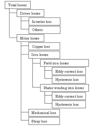
Fig.1: Classification of Losses
The iron losses can be classified into eddy current loss and hysteresis loss based on the magnetic generation principle. Other losses include mechanical loss and stray load loss. However, this discussion will disregard them, including those in the iron losses because they are small enough when compared with the iron and copper losses.
2.2. Field Iron Losses
Fig. 2 shows a structure of the stepper motor. A hybrid type stepper motor uses a permanent magnet for the rotor, and equips inductors called teeth on outer diameter of the rotor core and inner diameter of the stator core. The iron loss is generated when the rotor rotates because the teeth periodically face, and the flux in the stator core changes periodically. It is called field iron loss as stated above.
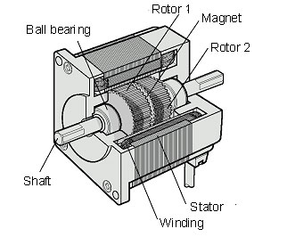
Fig.2: Structure of Stepper Motor
Fig. 3 shows a measurement system for the field iron losses. A torque meter is set between an external driving motor and a motor to be measured, and the rotor is rotated from outside. The rotational speed and the torque are measured, and the iron loss is calculated by the expression (1).
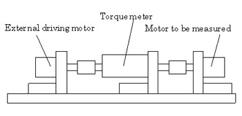
Fig.3: Measurement System of Field Iron Losses
W0 = (2π / 60) · N · T.................................. (1)
W0 : Field iron loss [W]
N : Rotating speed [r/min]
T : Torque [N・m]
As mentioned above, the iron losses consist of the eddy current loss and the hysteresis loss, and each loss per unit mass is expressed as follows.
We = ce · Bm2 · t2 · k2 · N2........................... (2)
Wh = ch · Bm1.6 · k · N............................... (3)
We : Eddy current loss [W/kg]
Wh : Hysteresis loss [W/kg]
ce, ch : Iron loss constant determined by material
t : Thickness of lamination sheet [mm]
k : Constant by number of pole pair
Bm : Flux density [T]
N : Rotating speed[r/min]
From those expressions, it is understood that the eddy current loss is proportional to the square of the rotational speed, and the hysteresis loss is proportional to the rotating speed. The iron loss is a sum of the eddy current loss and the hysteresis loss, and it is to be proportional to the 1st ~ 2nd power of the rotational speed. Fig. 4 shows a measurement result of field iron loss of the conventional motor. It is expressed by the expression (4) approximately, and is proportional to the 1.44th power of the rotational speed.
W0 = 7.84x10⁻⁴ · N1.44.............................. (4)
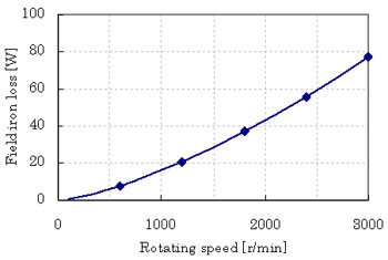
Fig.4: Field Iron Loss of Conventional Stepper Motor
2.3. Separation of Motor Losses
The configuration diagram of the loss measurement is shown in Fig. 5. A power meter is set between the power supply and the driver, and the driver and the motor respectively for measuring the power and the current.
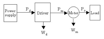
Fig.5: Configuration Diagram of Loss Measurement
The driver input, the motor input, and the output are assumed to be Pd, Pm, and Po respectively. The difference between the driver input and the output makes a total loss Wu, and difference between the motor input and the output makes a motor loss Wm. Each value is expressed by the following expressions.
Wu = Pd - Po............................................. (5)
Wm = Pm - Po............................................. (6)
The difference between the driver input and the motor input makes a driver loss Wd, and it is expressed by the following expression.
Wd = Pd - Po............................................. (7)
The stepper motor is controlled with a driver so that a constant current may flow regardless of load. Therefore, a smaller load causes a bigger loss.
Consequently, the loss evaluation of the stepper motor with no load is the severest. When assuming Po=0 in expression (5) and expression (6), the whole driver input results in a total loss, and the whole motor input results in a motor loss. Fig. 6 shows the no-load loss of the conventional stepper motor. It is understood that the motor loss is relatively large compared with the driver loss.
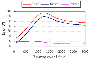
Fig.6: No-Load Loss of Conventional Stepper Motor
Next explained is the separation of the motor losses. As copper loss of the motor is calculated by the expression (8), the iron loss follows the expression (9).
Wc = n ·I2 · R............................................ (8)
Wfe = Wm - Wc........................................... (9)
Wc : Copper loss [W]
Wfe : Iron loss [W]
n : Number of phases
I : Current in RMS value [A]
R : Winding resistance [ohm]
Fig.7 shows the result of separating the conventional stepper motor’s loss from copper loss and iron loss. The motor current, the torque, and the field iron loss are described for reference.
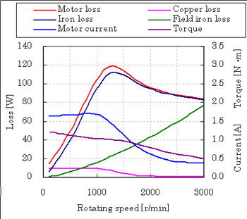
Fig.7: Motor Loss of Conventional Stepper Motor
Although the current of stepper motor is controlled to be at a constant value in the fixed current area of 1000r/min or less, the current decreases when at higher speed. This is because the voltage to operate the constant current control becomes insufficient because of an increase in impedance at high speed. The area where the current decreases is called constant voltage area.
Fig. 7 shows the max motor iron loss at about 1200r/min. Usually the iron loss when rotating is larger than the field iron loss because the stator winding iron loss is added to the field iron loss. Therefore, difference between the iron loss and the field iron loss is a stator winding iron loss. The stator winding iron loss decreases in the constant voltage area because the current is decreased. The conventional motor has a characteristic where the field iron loss becomes equal to the iron loss at about 3,000r/min.
Though the motor loss is the sum of iron loss and copper loss, the copper loss is relatively small, and the motor loss is almost equal to the iron loss at high speed. The maximum loss of the conventional motor is 119W, of which iron loss is 112W. That is 94% of the motor loss. Reduction of the iron loss is thought of as an effective development for lowering the loss of a stepper motor
3.Lower Loss Technology for a Stepper Motor
3.1. Lower Iron Loss by Suitable Lamination Sheet
The following methods can be expected from the expression (2) and the expression (3) for lowering the iron loss.
(i) Material with a small iron loss constant (ce, ch) is used.
(ii) Thin lamination sheet is used.
The above are possible by changing grade and thickness of the lamination sheet.
Iron loss per unit mass:
Lamination sheet 1>Lamination sheet 2> Lamination sheet 3 > Lamination sheet 4
Stator cores were made for trial purposes with the above four kinds of lamination sheets, and the result of their max loss compared is shown in Fig. 8. The vertical axis shows the ratio based on the motor loss of the lamination sheet 1. For comparing the loss by material, it was compared under the same condition of holding torque.
In general, the smaller the specified value in iron loss the higher-grade the lamination sheet, however the saturation flux density tends to decrease as well when the specified value in iron loss becomes small. When it is used for the motor, the torque becomes smaller. The current was adjusted to create a uniform torque. Therefore the smaller specified value in iron loss from the lamination sheet, the larger the copper loss.
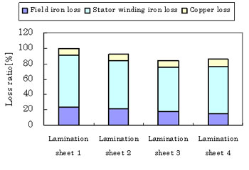
Fig.8: Relation of Lamination Sheet Material and Loss
The smaller the specified value in iron loss of the lamination sheet the smaller the field iron loss, however, it doesn't necessarily follow that the specified value in iron loss of the lamination sheet in the condition of a constant torque because the stator winding iron loss depends on the current. It reverses the iron loss value in the lamination sheet 3 and 4. The best lamination sheet was selected considering not only the specified value in iron loss of the lamination sheet but also the torque characteristic.
3.2. Lower Iron Loss by Suitable Fastening Method
Fig.9 shows the relationship of the fastening method and loss of the stator core (laminated core). Though the stator core is made of the lamination sheets to which insulation coating is given. Presently, fastening by dimples is the most common method.
Fig.9: Relation of Fastening Method of and Loss
The electrical insulation between the lamination sheets is broken down at the dimples. An eddy current becomes easy to flow due to this dielectric breakdown, and the eddy current loss grows more than the value calculated by expression (2). Fig. 9 shows the relationship of the fastening method and the maximum loss. The loss is different depending on the fastening method. The low loss stepper motor has adopted a fastening method with a small loss.
3.3. Practical Example
Fig. 10 shows the no-load loss of a low loss stepper motor and driver. Fig. 11 shows the loss comparison with the conventional stepper motor at the rotational speed where the total loss reaches its maximum value. The motor loss has decreased by 73%, and the driver loss by 26% when compared with the conventional stepper motor.
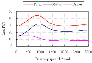
Fig.10: No-Load Loss of Low Loss Stepper Motor
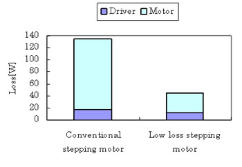
Fig.11: Stepper Motor and Driver Comparison in Loss
Fig. 12 shows the result in separating the motor loss of the low loss stepper motor into a copper loss and an iron loss. Field iron loss becomes bigger than iron loss at high speeds more than 2400r/min. This means that the current weakens the magnetic field and this condition is called field weakening.
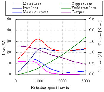
Fig.12: Motor Loss of Low Loss Stepper Motor
Fig. 13 shows the result in comparing the loss with the conventional stepper motor at the rotating speed that maximizes the motor loss. Though the copper loss has increased compared with the conventional stepper motor because the current is adjusted to make the torque uniform, the stator iron loss is reduced by 81%, the field iron loss by 73%, and the motor loss by 72% compared with the conventional stepper motor.
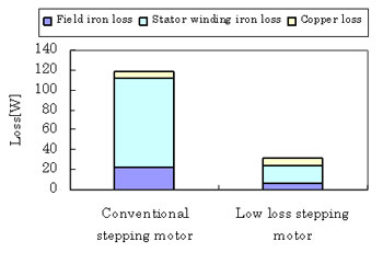
Fig.13: Comparison with Conventional Stepper Motor
Fig14 shows the temperature rise of motor case at the speed of maximum loss. At this measurement, a heat sink equivalent to an aluminum plate in 250mm x 250mm 6mm is attached. The temperature of the conventional stepping motor rose to over 60℃ in about 5 minutes. If rotation continued after that, the coils in the stator would burnout. On the other hand, the temperature of the low loss stepper motor is less than 60℃. The coils will not burnout.
4. Loss in Positioning Operation
When a heat sink equivalent to an aluminum plate of 250mm x 250mm x 6mm is attached, the permissible dissipation of the low loss stepper motor is about 40W at the ambient temperature. As the max dissipation of the low loss stepper motor is 32W, it is possible to drive it continuously in the above-mentioned condition.
However, we now discuss about the loss in a positioning operation because the stepper motor is used mainly for positioning operation.
4.1. Loss Characteristic
Fig.15 shows the relationship of the load and the rotating speed. For the stepper motor in Fig. 15, the peak value of the motor loss decreases when the load increases, however the change by the load is small, and the change by the rotating speed is larger.
The loss is expressed by a function of the rotating speed and the load torque. Therefore, the loss can be calculated from the torque and the rotating speed.
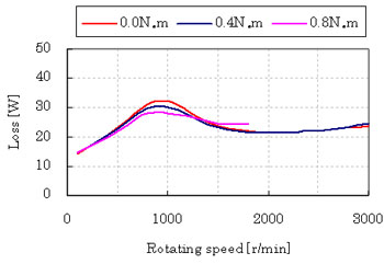
Fig.15: Loss Characteristic of Low Loss Stepper Motor
4.2. Loss Calculation
Fig. 16 shows the speed pattern in a typical positioning operation. This operation pattern accelerates up to a rotational speed Nm in acceleration time t1, then rotates at a constant speed over time t2, and decelerates in deceleration time t3, and stops. This operation pattern is called a trapezoidal drive, and the area of trapezoid shows the rotation amount. Usually, applications such as inspection and assembly, etc. are done in the stop time t4 after the completion of positioning, and the following operation is begun. Time tc is from a start-up to the following start-up and is called cycle time. When heat generation is large, it is necessary to set a longer stop time for cooling down.
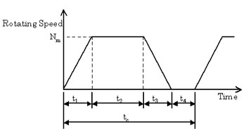
Fig.16: Speed Pattern in Positioning Operation
Fig. 17 shows the torque pattern when it is driven by the speed pattern in Fig. 16. Torque TL for the load torque component is necessary during a constant speed time, and acceleration torque Ta and deceleration torque Td are necessary during an acceleration/deceleration time.
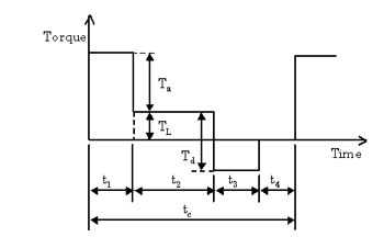
Fig.17: Torque Pattern in Positioning Operation
As described above, the stepper motor losses depend on the rotating speed, therefore the loss pattern can be shown in Fig. 18.
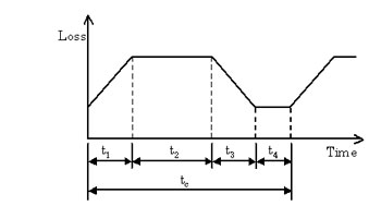
Fig.18: Loss Pattern in Positioning Operation
When the instantaneous maximum value of the loss is assumed to be w(t), average value of the loss per cycle is calculated by the following expression.
![]() ................................... (10)
................................... (10)
4.3. Calculation Result
The motor loss is calculated when the shortest positioning operation is done with an inertial load of J=2.5×10⁻⁴kg・m2 (90mm in outside diameter, 5mm in thickness, and material of iron) attached. Table 2 results by calculating the operation pattern of which positioning time is the shortest in consideration of the safety rate.Table.2: Operation Pattern
Rotation amount [Rotation] |
Acceleration/ |
Rotating speed |
Positioning time[ms] |
0.1 |
14 |
400 |
29 |
0.5 |
30 |
800 |
68 |
1 |
40 |
1000 |
100 |
2 |
59 |
1300 |
152 |
5 |
100 |
1800 |
267 |
10 |
146 |
2200 |
419 |
From expression (10), the loss in each operation pattern is calculated, and Fig. 19 shows a calculation result of the speed pattern and the loss when the rotation amount is two rotations, as an example.
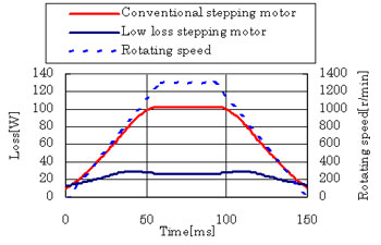
Fig.19: Calculation Example
Fig. 20 shows the relationship between the rotation amount and the motor loss. When the rotation amount is 0.1, the difference of the loss is not so much. But, when rotation amount is increased, the difference becomes large.
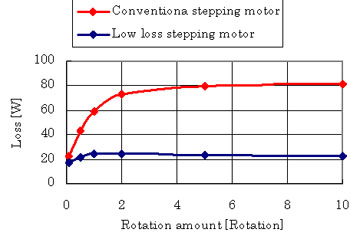
Fig.20: Relation of Rotation Amount and Motor Loss
For the conventional stepping motor, intermittent operation or fan cooling is needed even when a positioning operation is conducted because the loss increases to about 80W when the rotation amount is increased. For the low loss motor, a stop time for cooling is unnecessary because the losses are only about 24W even when the rotation amount is increased. Therefore, a continuous positioning operation is achieved for any rotation amount.
5. Summary
Though the conventional stepper motor had a problem with large heat generation, the loss of the stepper motor will be reduced greatly by the lower loss technology. It has become possible to use a stepper motor in applications that require continuous motion at a constant speed, something not possible until now. The number of applications that a stepper motor may be suitable for will certainly increase. In application, these motors are very effective for energy savings.
Absolute Encoder Stepper Motors
Closed Loop Stepper Motors
5-Phase Stepper Motors