Stepper Motors > Technology > Speed - Torque Curves for Stepper Motors
Speed - Torque Curves for Stepper Motors
How They are Created and What They Mean
When selecting a stepper motor, you try to pick a motor that meets your speed and torque requirements plus some safety margin. But how do you compare motor performance between motor suppliers. Most suppliers provide speed – torque characteristic curves to provide an idea of what performance can be expected from a motor. Stepper motor speed - torque curves show how much torque is available from a stepper motor at a given speed when combined with a particular driver. This means that depending on different motor and driver combinations, different performance can be expected from the stepper motor system. This article will describe how a speed - torque curve for a stepper motor is generated and what are the important points to look for on a curve.
A well defined speed – torque curve, such as the ones shown below, should include the following information.
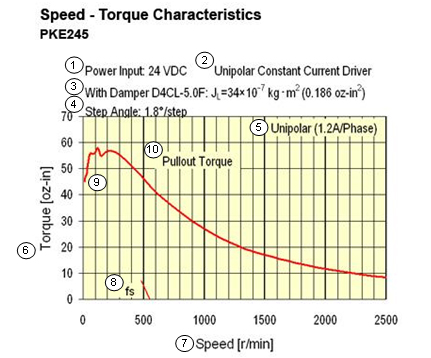
1. Power input: This is the voltage that is supplied to the driver. For DC input voltage drivers, this same voltage is usually applied directly to the motor windings. For AC input voltage drivers, the AC voltage is rectified to a DC voltage before being applied to the motor windings. For example, for an 115VAC driver, the applied voltage to the motor windings is 162VDC.
2. Driver type: This states what type of driver was used to create the curve. Either a unipolar or bipolar driver should be shown. The driver type will also states if the driver is of the constant current or constant voltage type.
3. Damper use: While not required, a damper can help to create a more typical performance curve by representing an inertial load on the motor. The curve should state if a damper was used and what its characteristics are.
4. Step angle: This is the step angle the motor was driven at when creating the curve. Curves will commonly show what the basic step angle (1.8°, 0.9°, 0.72°, 0.36°) of the motor or what driver resolution (full, half, microstep divisions) were used.
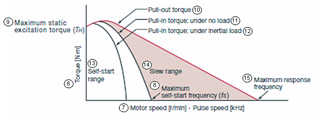
5. Motor winding configuration: This describes how the motor was connected to the driver and what current was applied to the windings. Motor connections could be unipolar, bipolar series, bipolar half coil and bipolar parallel.
6. Torque units: The vertical axis shows the amount of torque and in what units (e.g. oz-in, N-m, etc).
7. Speed: The horizontal axis shows the shaft speed of the motor and in what units (e.g. rpm, pps, Hz, etc).
8. Maximum No-load starting speed: The maximum no-load starting speed is the maximum speed at which the motor can be started in synchronism with no load attached and no acceleration used. It is usually shown as a tick mark labeled “fs” on the horizontal axis.
9. Holding Torque: This is the torque that the motor will produce when the motor is at rest and rated current is applied to the windings.
10. Pull-out Torque curve: This curve represents the maximum torque that the stepper motor can supply to a load at any given speed. Any torque or speed required that exceeds (goes above) this curve will cause the motor to lose synchronism.
11. Pull-in Torque curve (no load): This curve represents the maximum torque and speed combination that an unloaded stepper motor can start or stop without any acceleration or deceleration. Since the pull-in torque curve for a stepper motor varies depends on the inertial load attached to the motor, the pull-in torque curves are not shown in the speed – torque curves shown in catalogs. In order to operate above the pull-in torque curve, the motor must be accelerated into or decelerated out of the slew range.
12. Pull-in Torque curve (inertial load): This curve represents the maximum torque and speed combination that a stepper motor with an inertial load (i.e. damper) can supply to a load and start or stop without any acceleration or deceleration. In order to operate above the pull-in torque curve, the motor must be accelerated into or decelerated out of the slew range.
13. Self start range (start/stop region): When in this area, the stepper motor can start, stop or change directions in synchronism with the input pulse without the need for acceleration or deceleration.
14. Slew range: The slew range is where stepper motors are usually operated. A stepper motor can not be started directly in the slew range. After starting the motor somewhere in the self start range, the motor can be accelerated into or load applied into the slew range. The motor must then be decelerated or load reduced back into the self start range before the motor can be stopped.
15. Maximum response frequency: This is the maximum speed the motor can be operated when no load is applied to the shaft.
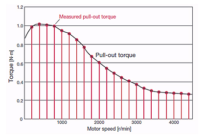
The speed – torque curves are created by spinning a step motor up to a known speed and then gradually applying torque to the output shaft with a brake and measured with a torque transducer. The load is slowly applied until the motor loses synchronism (stops). At the moment that the motor loses synchronism, the torque that was applied to the motor shaft at that same moment is recorded. This process is repeated three times at each speed point. The average of the three torque values is then used as the value that will be displayed on the speed – torque curve. This process is repeated at several speed points. The torque points are then plotted at the various speed points to create the complete curve. See figure below.
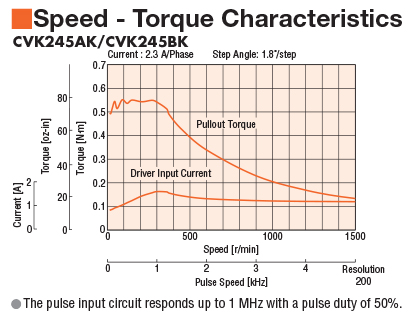
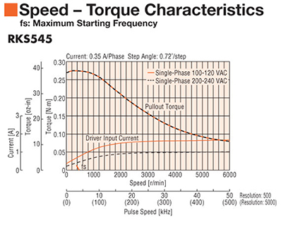
As was mentioned earlier, the speed – torque characteristics are determined by the stepper motor and driver combination. In general, the higher the applied voltage to the motor windings, the faster the motor will rotate. For example, in the curves below, the speed – torque curve for the CVK245AK/CVK245BK stepper driver indicates that 24VDC is applied to the motor windings, while the curve for the RKS545 stepper driver was created with 162VDC being applied to the windings. As you can see, the torque at speed of the RKS545 stepper driver is held out to a much higher speed.
In summary, the speed- torque curve can be a useful tool for selecting the right stepper motor for your application.
Nick Johantgen
North American Technical Product & Training Manager
Oriental Motor USA Corporation
2-Phase Bipolar Stepper Motors
5-Phase Stepper Motors
Closed Loop Stepper Motors