Products
Solutions
Technical Information
Motor Sizing
Downloads
Contact Us
Brushless DC Motors & Gear Motors > Technology > Speed Control Systems Overview
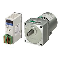
Speed Control Systems (Brushless DC Motor & AC Motor) Overview
Brushless DC Motor Structure and Principle of Operation
Structure of Brushless DC Motor
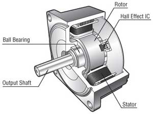
The brushless DC motor has a built-in magnetic element or optical encoder for the detection of rotor position. The position sensors send signals to the drive circuit. The brushless motor uses three phase windings in a "star" connection. A permanent magnet is used in the rotor.
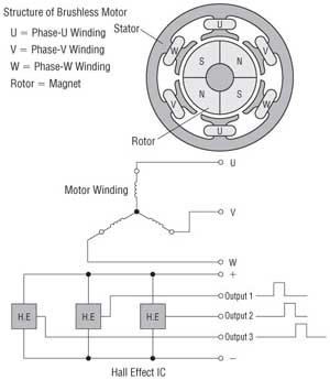
A Hall effect IC is used for the sensor's magnetic element. Three Hall effect ICs are placed within the stator, and send digital signals as the motor rotates.
• Drive Method of Brushless DC Motors
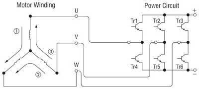
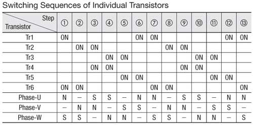
The motor windings are connected to switching transistors, six of which make up the inverter. The top and bottom transistors turn on and off, according to a predetermined sequence, to change the direction of current flow in the windings.
The mechanism of brushless DC motor rotation can be described as follows: In step 1 of the transistor's switching sequence, as shown in the following figure, transistors Tr1 and Tr6 are in the "ON" state.
At this time the winding current flows from phase U to phase W, and phases U and W are excited so that they become N and S poles, respectively, thus causing the rotor to turn 30˚. Repeating such a motion 12 times thereby facilitates rotation of the motor.
• Control Method of Brushless DC Motors
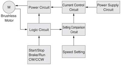
The drive circuit of the brushless DC motor is connected in the
configuration shown in the figure below, and is comprised of five
main blocks.
•Power circuit
•Current control circuit
•Logic circuit
•Setting comparison circuit
•Power supply circuit
• Power Circuit
This circuit uses six transistors to control the current flow in the motor windings. The transistors provided at the top and bottom turn on and off repeatedly according to a predetermined sequence, thereby controlling the current flow to the motor windings.
• Current Control Circuit
The current flow to the motor varies according to the load. It is constantly detected and controlled so that the speed will not deviate from the set speed.
• Logic Circuit
The logic circuit detects the rotor position by receiving feedback signals from the motor's Hall effect IC and determines the excitation sequence of motor windings. The circuit signal is connected to each transistor base in the power circuit, driving the transistors according to a predetermined sequence. It also detects the motor's speed.
The logic circuit is also used to control commands to the motor, including start/stop, brake/run and CW/CCW.
• Setting Comparison Circuit
This circuit compares the motor speed signal against the speed setting signal in order to determine whether the motor speed is higher or lower than the set speed. The input to the motor is lowered if the motor speed is higher than the set speed, but the input is raised if it is lower than the set speed. In this manner, the speed that has varied is returned to the set speed.
• Power Supply Circuit
This circuit converts a commercial power supply into the voltage necessary to drive the motor and control circuits.
Speed Control Methods of AC Motor Systems
The basic block diagrams and outline of the control methods are shown below. AC speed control motors employ a closed-loop control system, while inverters employ an open-loop control system.
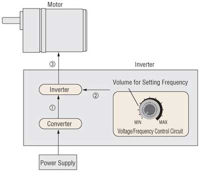
• Inverters
◇ BHF Series, FE100/FE200
Control Method
-
1. Input from the AC power supply is rectified, and output as DC voltage.
2. A voltage signal led by the frequency set with the volume for setting frequency is output.
3. Voltage of the set frequency is applied to the motor.
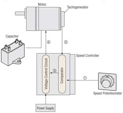
• AC Speed Control Motors
◇ ES01/ES02, US Series
Control Method
1. The speed setting voltage is supplied via a speed potentiometer.
2. The motor speed is detected and the speed signal voltage is supplied.
3. The difference between the speed setting voltage and speed signal voltage is output.
4. A voltage determined by the output from the comparator is supplied to the motor so that it will reach the set speed.
Speed-Torque Characteristics of Speed Control Systems
• Brushless Motor Systems
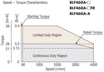
The figure below illustrates the characteristics example of a BLF Series motor. The BX Series, BLU Series and BLH Series motors also have similar characteristics, although their speed control ranges are different.
Brushless motors generate constant rated torque from 80 to 4000 r/min, with the same starting torque as rated torque. (With the BLF Series and BLH Series, the output torque at the maximum speed is less than rated torque.) Unlike AC speed control motors, torque in a brushless motor will not drop at low speeds, so brushless motors can be used at rated torque from high to low speeds.
In addition to continuous duty region, brushless motors also have limited duty region. The torque generated in the limited duty region, which is 1.2 times the rated torque (2 times for the BX Series and BLF Series), is effective for starting inertial load. If operated for more than approximately five seconds in the limited duty region, the overload protective function of the driver may engage and the motor will coast to a stop.
• Inverters
The speed – torque characteristics shown in the figure below is typical for all inverters.
The speed of an inverter varies depend on the frequency of the voltage applied to the motor. Accordingly, the speed also changes due to the load torque, which is equal to the induction motor.

AC Speed Control Motors
The speed – torque characteristics shown in the figure below is typical for all AC speed control motors.
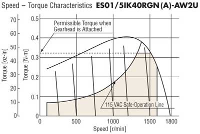
• Safe-Operation Line and Permissible Torque When Gearhead is Attached
Input power to the speed control motor varies with the load and speed. The greater the load, and the lower the speed, the greater an increase in motor temperature.
In the speed – torque characteristics of AC speed control motor and inverter, there is the safe-operation line, while the area below the line is called the continuous duty region.
The safe-operation line, measured by motor's temperature, indicates its limit for continuous operation (30 minutes operation for a reversible motor) with the temperature level below the permissible maximum.
Whether the motor can be operated at a specific load and speed is determined by measuring the temperature of the motor case. In general, when the motor case temperature is 90˚C (194˚F) or less, continuous operation is possible, considering the insulation class of motor winding. It is recommended that the motor be used under conditions that keep the motor temperature low, since the motor life is extended with lower motor temperature.
When using a gearhead, be aware that it is necessary to operate below the torque in the "gearmotor – torque table." If the actual torque required exceeds this torque, it may damage the gearhead and shorten its life.
• Variable Speed Range (Speed ratio) and Load Factor
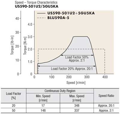
When the ratio of minimum speed and maximum speed of an AC speed control motor is given as the motor's speed ratio, the speed ratio increases to as much as 20:1 in a range where the load factor (ratio of load torque to starting torque) is small (Refer to the 20% load factor range in the diagram to the right). This widens the motor's range of operation.
If the load factor is high, the speed ratio becomes low.
◇ Load Factor and Speed Ratio
The following explains the relationship of load factor and speed ratio. Usually, a motor is often used in combination with a gearhead. The following assumes such a configuration.
The following table shows the continuous duty region and speed ratio of the US Series at load factors of 20% and 50%, as read from the diagram. Although the speed ratio is large when the load factor is 20%, it decreases when the load factor is 50%. As shown, generally AC speed control motors do not have a wide speed range.
To operate your motor over a wide speed range, choose a type that offers high starting torque (a motor with the next larger frame size). With a brushless motor, the operation speed range remains wide regardless of the load factor, as indicated by the dotted line.
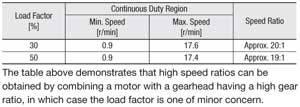
◇ Speed Ratio When a High Ratio Gearhead is Used
Since the starting torque is also limited by the maximum permissible torque of the gearhead, the load factor of a gearhead with a high gear ratio is determined by the load torque with respect to the maximum permissible torque of the gearhead.
In the previous example, a gearhead with a gear ratio of 5:1 was used. The diagram below shows when a gearhead with a gear ratio of 100:1 is used.
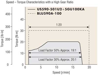
The maximum permissible torque of the 5GU100KA, which has a gear ratio of 100:1, is 20 N・m (177 lb-in). The speed ratios at load factors of 30% and 50% are shown in the table below:
Brushless DC Motor & Drivers
AC Speed Control Motors