Products
Solutions
Technical Information
Motor Sizing
Downloads
Contact Us
Stepper Motors
Stepper Motors, Stepper Motor Drivers and Controllers
Stepper Motors, Stepper Motor Drivers and Controllers
Stepper motors enable accurate positioning with ease. They are used in various types of equipment for accurate rotation angle and speed control using pulse signals. Stepper motors generate high torque with a compact body, and are ideal for quick acceleration and response. Stepper motors also hold their position at stop, due to their mechanical design. Stepper motor solutions consist of a driver (takes pulse signals in and converts them to motor motion) and a stepper motor.
Oriental Motor offers many solutions for a wide variety of applications:
- αSTEP Closed Loop Stepper Motors, 2-Phase Stepper Motors, 5-Phase Stepper Motors
- Geared, Encoder and Electromagnetic Brake options
- AC or DC Input Stepper Motor Drivers
- Frame Sizes from 0.51 in. (13 mm) up to 3.54 in. (90 mm)
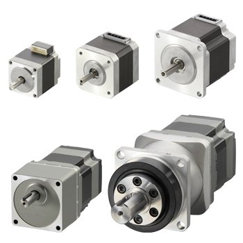
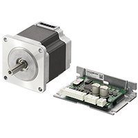
Stepper Motors (Motor Only)
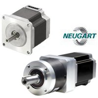
Oriental Motor offers a wide range of stepper motors including; αSTEP closed loop stepper motors, 2-phase stepper motors and 5-phase stepper motors available in frame sizes from 0.79 in. (20 mm) up to 3.54 in. (90 mm). Five geared type stepper motor solutions, encoder and brake options and various motor windings are offered.
- 0.51 in. ~ 3.54 in. (13 mm~ 90 mm) NEMA 5 ~ NEMA 34 frame size stepper motors
- Non-backlash, Low-backlash and Spur Gears available
- αSTEP Closed Loop Stepper Motors, 2-Phase Stepper Motors and 5-Phase Stepper Motors
- Encoder and Electromagnetic Brake Options
- Vacuum Rated (10-5 to 10-4 Pa) Stepper Motor Options
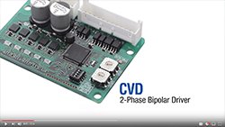
Stepper Motor Drivers
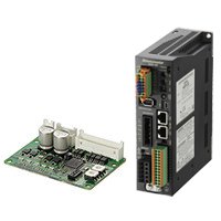
Stepper motor drivers convert pulse signals from the controller into motor motion to achieve precise positioning.
- AC or DC Input
- αSTEP Closed Loop Stepper Motors, 2-Phase Stepper Motor or 5-Phase Stepper Motor Drivers
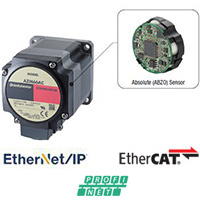
- Pulse Input, Built-in Controller or EtherNet/IP™, EtherCAT, PROFINET Compatible versions
- Board or Box Type
![]()
![]()
![]()
EtherNet/IP™ is a trademark of ODVA
Speed Control Stepper Motors & Drivers
The CVK Series SC speed control system offers a simple configuration consisting of a stepper motor, driver and programmable controller. The operating speed, acceleration and deceleration time, running current can be set via the driver switches, and simply turning the FWD (RVS) input to ON or OFF allows for easy control.
- No pulse generator needed
- 2 speed settings are possible
- Compact and high torque stepper motor
Network Gateways
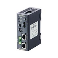
Network Gateways for use with motion control systems.
- Network Converters/Gateways (RS-485 Communication)
- EtherCat
- CC-Link
- MECHATROLINK
![]()
![]()
![]()
Stepper Motors & Drivers
A stepper motor is used to achieve precise positioning via digital control. The motor operates by accurately synchronizing with the pulse signal output from the controller to the driver. Stepper motors, with their ability to produce high torque at a low speed while minimizing vibration, are ideal for applications requiring quick positioning over a short distance.
Accurate Positioning in Fine Steps
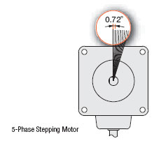
A stepper motor rotates with a fixed step angle, just like the second hand of a clock. This angle is called "basic step angle". Oriental Motor offers stepper motors with a basic step angle of 0.36°, 0.72°, 0.9° and 1.8°. 5-Phase stepper motors offer 0.36° and 0.72°, while 2-Phase stepper motors offer 0.9° and 1.8° step angles.
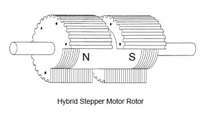
Utilizing Hybrid Stepper Motor Technology
A hybrid stepper motor is a combination of the variable reluctance and permanent magnet type motors. The rotor of a hybrid stepper motor is axially magnetized like a permanent magnet stepper motor, and the stator is electromagnetically energized like a variable reluctance stepper motor. Both the stator and rotor are multi-toothed.
A hybrid stepper motor has an axially magnetized rotor, meaning one end is magnetized as a north pole, and the other end a south pole. Toothed rotor cups are placed on each end of the magnet, and the cups are offset by half of a tooth pitch.
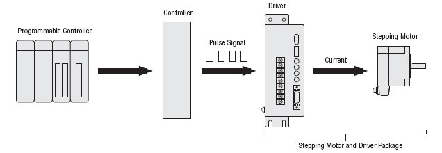
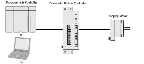
Easy Control with Pulse Signals
A system configuration for high accuracy positioning is shown below. The rotation angle and speed of the stepper motor can be controlled with precise accuracy by using pulse signals from the controller.
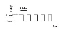
What is a Pulse Signal?
A pulse signal is an electrical signal whose voltage level changes repeatedly between ON and OFF. Each ON/OFF cycle is counted as one pulse. A command with one pulse causes the motor output shaft to turn by one step. The signal levels corresponding to voltage ON and OFF conditions are referred to as "H" and "L" respectively.
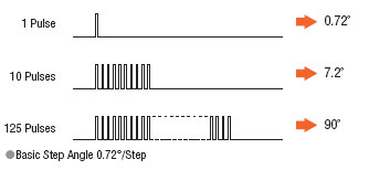
The Amount of Rotation is Proportional to the Number of Pulses
The amount the stepper motor rotates is proportional to the number of pulse signals (pulse number) given to the driver. The relationship of the stepper motor's rotation (rotation angle of the motor output shaft) and pulse number is expressed as follows:
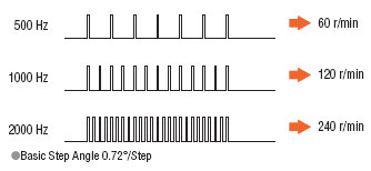
The Speed is Proportional to the Pulse Speed
The speed of the stepper motor is proportional to the speed of pulse signals (pulse frequency) given to the driver. The relationship of the pulse speed [Hz] and motor speed [r/min] is expressed as follows:
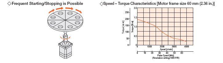
Generating High Torque with a Compact Body
Stepper motors generate high torque with a compact body. These features give them excellent acceleration and response, which in turn makes these motors well-suited for torque-demanding applications where the motor must start and stop frequently. To meet the need for greater torque at low speed, Oriental Motor also has geared motors combining compact design and high torque.
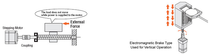
The Motor Holds Itself at a Stopped Positioning
Stepper motors continue to generate holding torque even at standstill. This means that the motor can be held at a stopped position without using a mechanical brake.
Once the power is cut off, the self-holding torque of the motor is lost and the motor can no longer be held at the stopped position in vertical operations or when an external force is applied. In lift and similar applications, use an electromagnetic brake type.
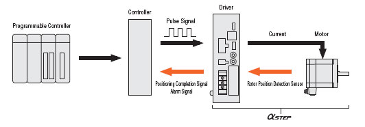
Closed Loop Stepper Motors and Drivers - αSTEP
The αSTEP consists of stepper motor and driver products designed to draw out the maximum features of a stepper motor. These products normally operate synchronously with pulse commands, but when a sudden acceleration or load change occurs, a unique control mode maintains positioning operation. αSTEP models can also output positioning completion and alarm signals, which increase the reliability of the equipment which they operate.
Types of Operation Systems
Each stepper motor and driver combines a stepper motor selected from various types, with a dedicated driver. Drivers that operate in the pulse input mode and built-in controller mode are available. You can select a desired combination according to the required operation system.
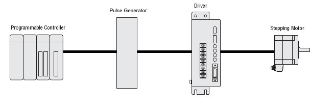
Pulse Input Driver
The motor can be controlled using a pulse generator provided by the user. Operation data is input to the pulse generator beforehand. The user then selects the operation data on the host programmable controller, then inputs the operation command.
Built-in Controller Driver
The built-in pulse generation function allows the motor to be driven via a directly connected personal computer or programmable controller. Since no separate pulse generator is required, drivers of this type save space and simplify wiring.
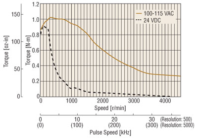
Difference Between AC Input and DC Input Characteristics
A stepper motor is driven by a DC voltage applied through a driver. In Oriental Motor's 24 VDC input motor and driver systems, 24 VDC is applied to the motor. In the 100-115 VAC motor and driver systems, the input is rectified to DC and then approximately 140 VDC is applied to the motor (certain products are exceptions to this.)
This difference in voltage applied to the motors appears as a difference in torque characteristics at high speeds. This is due to the fact that the higher the applied voltage is, the faster the current rise through the motor windings will be, facilitating the application of rated current at higher speeds. Thus, the AC input motor and driver system has superior torque characteristics over a wide speed range, from low to high speeds, offering a large speed ratio.
It is recommended that AC input motor and driver systems, which are compatible over a wider range of operating conditions than DC input systems, be considered for your application.
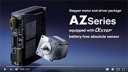
αSTEP AZ Series Product Family
Stepper Motor Videos
Stepper Motor Technical Articles
- Hybrid Stepper Motors and αSTEP Hybrid Control Systems
- Eliminating External Sensors with the αSTEP AZ Series Absolute Encoder Stepper Motors
- Everything You Need to Know about Stepper Motors
- 2-Phase vs. 5-Phase Stepper Motors
- Overcoming Rotation Vibration
- Development of the αSTEP Battery-Free, Multi-Rotation Absolute Mechanical Encoder
- Speed-Torque Curves of Stepper Motors
- Stepper Motor Lower Loss Technology Development
- IP Ratings - Degree of Protection
- Motor Sizing Calculations
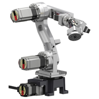
Industrial Robots
Download Product Literature