Products
Solutions
Technical Information
Motor Sizing
Downloads
Contact Us
Linear Actuators > Technology > Calculating Moment Loads on Linear Actuators
Method for Calculating Moment Loads on Linear Actuators
An electric linear actuator is a combination product consisting of a linear mechanism and an electric motor, and when pre-assembled offers an easier design, shorter installation time, and high quality.
While the actuator is operating, moment loads occur due to not only gravity, but also because of acceleration and deceleration of the load. Because moment loads can damage actuators, confirming that they are within specification is critical. However, calculating moment loads on linear actuators can be complicated and time consuming.
This paper describes a method for calculating moment loads in a simple way and makes actuator selection easier.
1. Introduction
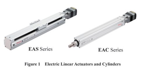
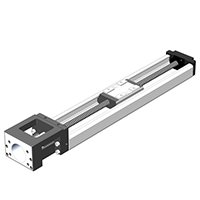
By combining a motor with linear mechanical components, electric linear actuators benefit design engineers by shortening the time to design, install and adjust the equipment (Refer to Figure 1).
When electric linear actuators are in operation, moment loads occur due to gravity applied to the load and the acceleration of the load. Because moment loads have great influence on the service life of actuators, it is essential to make sure that they are within the actuator specifications. However, calculating moment loads of electric linear actuators can be complicated and time consuming, because installation directions and motions are typically considered for linear actuators.
2. Selection of Linear Actuators (The Concept of Moment Leads)
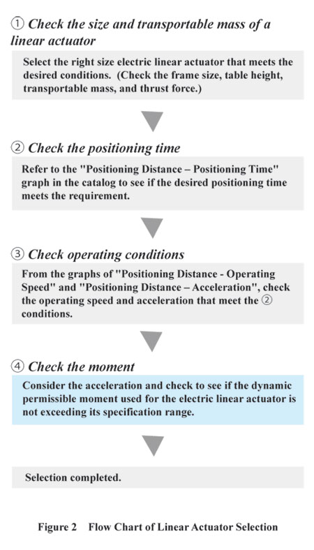
Figure 2 shows the flow of linear actuator selection. First, check the size and transportable mass of a linear actuator. Next, check the positioning time in order to determine operating conditions that meet the required positioning time. Lastly, check to see if the moment applied to the actuator is within the permissible range.
3. Structure of Electric Linear Actuators
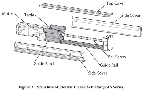
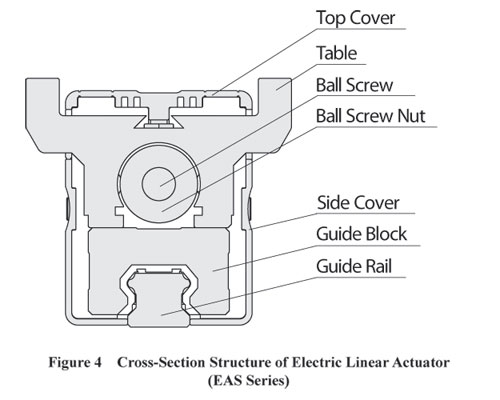
Using the EAS Series as an example, the structure of electric linear actuator is shown in Figure 3. Also, Figure 4 shows its cross-section structure.
The load applied to a table and moment loads are all supported by a linear guide consisting of a guide rail and guide block.
These loads have an influence on the life of the linear guide and thus, are important to consider during the selection process.
4. Moment Applied to Actuator
The moment applied to an electric linear actuator is explained in the next section.
4.1. Moment Applied to Electric Linear Actuator
As shown in Figure 5, when the center of gravity of the carried load is overhung from the center of the table of the electric linear actuator, the moment is applied from the center of the table as the support point. The moment applied to an electric linear actuator can be obtained from the following formula.
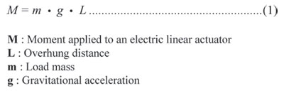
From this point forward, the gravitational acceleration is deemed 9.807m/s² in this article.
4.2. Moment Direction
There are three different directions of moments applied to electric linear actuator: pitching direction, yawing direction and rolling direction (Refer to Figure 6). The moment support points are on the bottom face (installation surface) of the linear actuator and the center of the table.

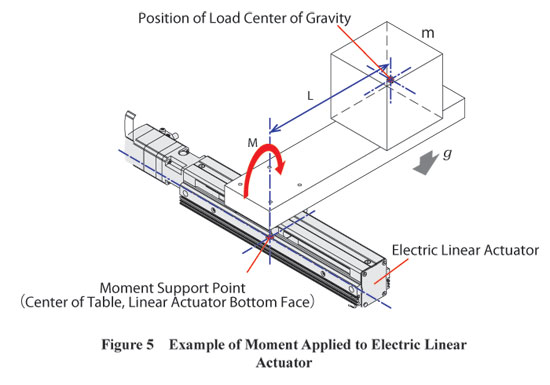
4.3. Moment Direction Determined by Installation Direction
Directions of moments applied to electric linear actuators can change depending on the installation condition of the load and the installation direction of the actuator itself. Figure 7 shows how the direction of a moment changes when the installation direction of an actuator is changed under the same installation condition of the load.
4.4. Static Permissible Moment and Dynamic Permissible Moment
4.4.1. Static Permissible Moment
The moment applied to the stopped linear actuator is called the static moment. The permissible value of the static moment of a linear actuator is called the static permissible moment and it is determined by the mechanical strength factors of a linear guide and table. When an external force is applied while the linear actuator is stopped, it is necessary to check that the static moment is within the permissible range at each direction.
4.4.2. Dynamic Permissible Moment
The moment applied to the linear actuator while transporting a load is called the dynamic moment. Because acceleration is applied during operation, the moment is applied depending on the overhung distance from the table.
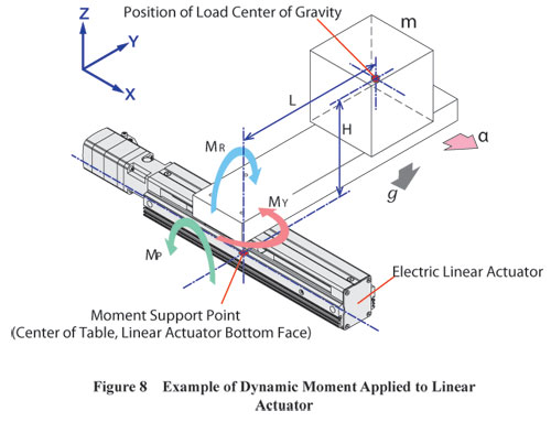
The calculation methods of the moment at each direction, when transporting a load with a linear actuator as shown in Figure 8, are shown in the proceeding formulas.
Each denotation in Figure 8 indicates the meaning as follows:
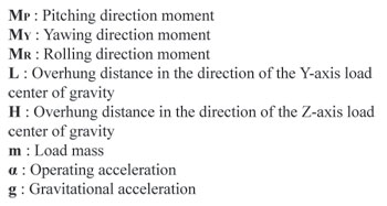
The mass of the arm and the position of the center of gravity are omitted in this figure.
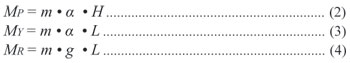
Formula 2 calculates the pitching direction moment; formula 3 calculates the yawing direction moment; and formula 4 calculates the rolling direction moment.
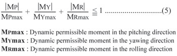
Calculate the ratio by dividing the moment values calculated by these formulas (2), (3), and (4) with the dynamic permissible moments at each direction, which are the product specifications. Next, add all of the calculated moment ratios at each direction. If the total sum is less than 1, as shown in the moment formula (5), then it can be used.
5. Moment Loads Calculation Example of Single Shaft Linear Actuator
In this section, moment loads calculation examples are explained per installation direction. A single shaft linear actuator is used as an example. The following shows a calculation example of moment loads when selecting the EASM4XD020ARAC electric linear actuator with a slide width of 45mm (1.771 in.) and table height of 60mm (2.362 in.):
5.1. When Installing in Horizontal Direction
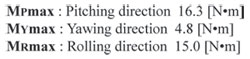
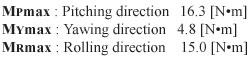
Figure 9 shows an electric linear actuator installed horizontally with the load overhung in the direction of the Y-axis. The dynamic permissible moment of the electric linear actuator is shown below:
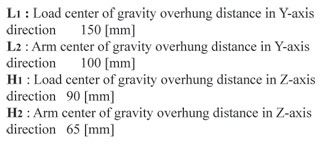
The load center of gravity from the actuator and the overhung distance of the arm's center of gravity are shown below:
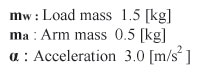
The load mass, arm mass, and acceleration are shown below:
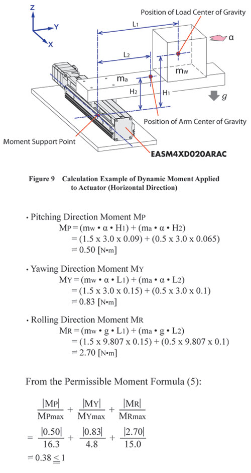
Based on the results, the moment is within the dynamic permissible moment and thus, it can be used.
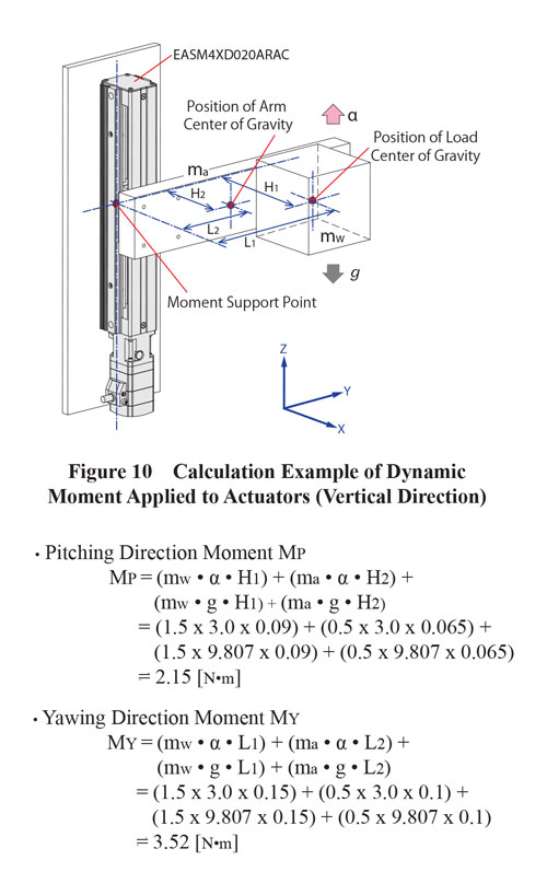
5.2. When Installing in Vertical Direction
Figure 10 shows a calculation example of the dynamic moment when a linear actuator is installed in the vertical direction. Installation dimensions, loads, and operating conditions are exactly the same as 5.1.
The rolling direction moment MR is not applied, thus it is 0 [N·m]. From the Permissible Moment Formula (5):
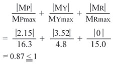
Based on the results, the moment is within the dynamic permissible moment and thus, it can be used.
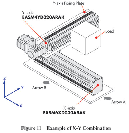
6. 2 Method of Moment Loads Calculation When Combining 2 Axes
Next, as an example of combining 2 axes, the moment loads calculation of the X-Y combination of electric linear actuators is explained.
With the X-Y combination, the single Y-axis, which transfers the load, is calculated first, in order to determine whether the Y-axis is usable. Then, for the calculation of moment loads of the X-axis, the moment load of the total mass of the Y-axis and the moment load generated when the Y-axis accelerates to transfer the load are added to the calculation.
Figure 11 shows an example of the X-Y combination of electric linear actuators. EASM6XD030ARAK is fixed on the X-axis slide and EASM4YD020ARAK is combined on the Y-axis. The Y-axis is fixed on the Y-axis fixing plate, and then fixed on the X-axis table.
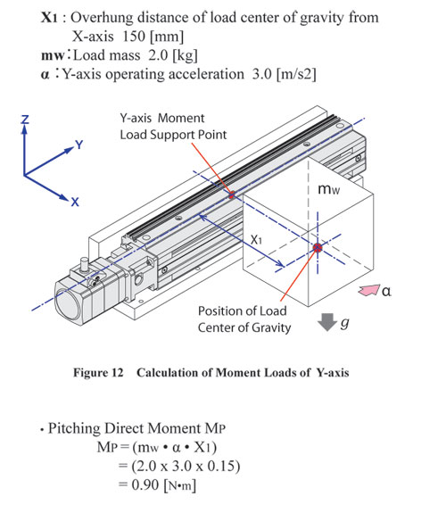
1) Calculation of Moment Loads for Y-axis
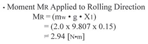
First, the moment load applied to the Y-axis is calculated (Refer to Figure 12). The dynamic permissible moments of the Y-axis actuator EASM4YD020ARAK are indicated below.
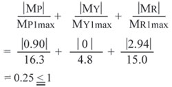
The overhung distance of the load center of gravity from the Y-axis, load mass, and acceleration of the Y-axis are indicated as follows.
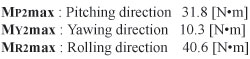
Because the moment MY is not applied to the yawing direction, it is 0 [N·m].
From the Permissible Moment Formula (5):
The moment of the Y-axis slide is within the specification range and thus, it can be used.
2) Calculation of Moment Loads for X-axis
Next, the moment load applied to the X-axis slide is calculated. The dynamic permissible moments of the X-axis slide EASM6XD030ARAK are indicated below.
The load from the X-axis, load center of gravity of the Y-axis, and overhung distance of the load center of gravity of the Y-axis slide fixed plate are indicated as follows.
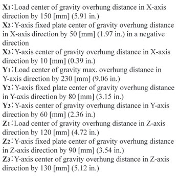
The mass of the Y-axis fixed plate, mass of the Y-axis slide, and X-axis operating acceleration are indicated as follows.
Figure 13 shows the arrow A in Figure 11, and Figure 14 shows the arrow B in Figure 11.
![]()
![]()
When calculating moment loads, simulate the condition of the moment load applied to the X-axis at its maximum, and calculate under the condition when the Y1 is at its peak.
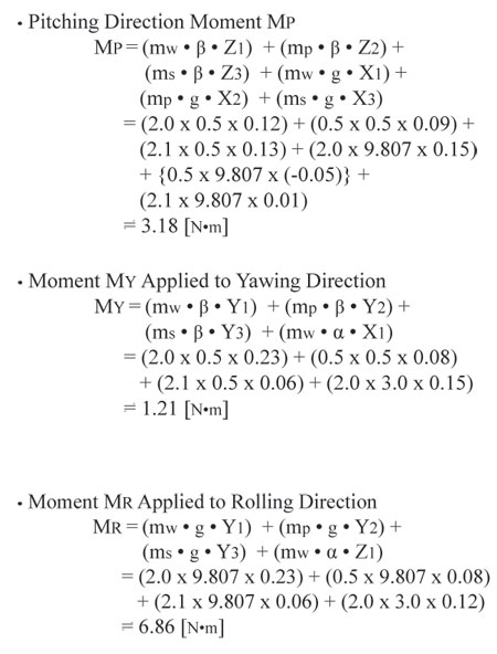
The moment applied to the X-axis is below the specification value and thus, it can be used. Based on the findings, both the X and Y axes meet respective dynamic permissible moments and therefore, it is determined that they are usable. The same steps of calculations are taken for the X–Y–Z combination with the addition of a Z-axis; start calculating the moment from the endmost axis, which is the Z-axis, then move on to the Y-axis and the X-axis.
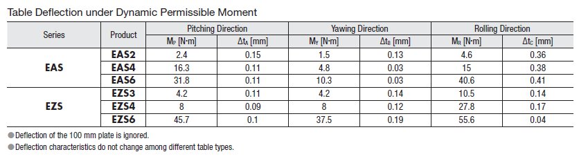
7. Deflection of When Moment is Applied to a Table
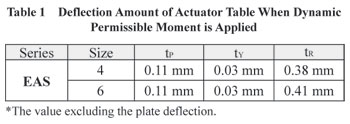
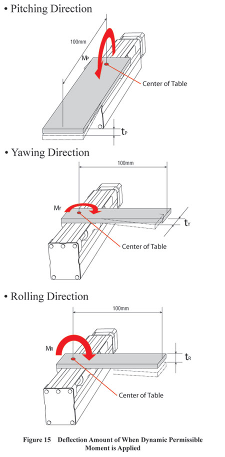
When the moment is applied to the slide, the table inclines in the moment direction. This inclination causes displacement to the overhung position. Table 1 shows the deflection amount when applying the dynamic permissible moments in each direction to the EAS Series slide table, as shown in Figure 15. The measurements are taken at the overhung position of 100mm (3.94 in.) from the center of the table, and the values are for reference only.
8. Calculation of Moment Loads for Electric Cylinders
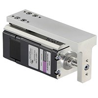
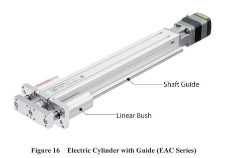
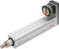
When using an electric cylinder, it is necessary to externally install a guide to support the rod so that it can support the moment loads. The series of an electric cylinder with a guide (shaft guide) that can be used while applying loads to the rod is also available (Refer to Figure 16). In this section, calculation examples of moment loads for an electric cylinder with a guide are explained.
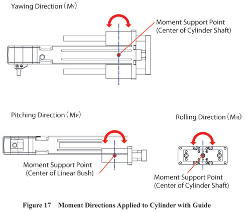
8.1. When Moment is Applied to Electric Cylinder with Guide
For an electric cylinder with a guide, there are directions for which moments are applied, just like an electric linear actuator. Figure 17 shows the moment directions which are applied to the cylinder with a guide.
8.2. Moment Loads Calculation of Electric Cylinder with Guide
8.2.1. Transferring Loads in Vertical Direction
A calculation example of moment loads applied to a linear bush, when a cylinder with a guide transfers loads in the vertical direction, is shown below. The following are shown in Figure 18.
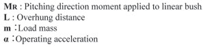
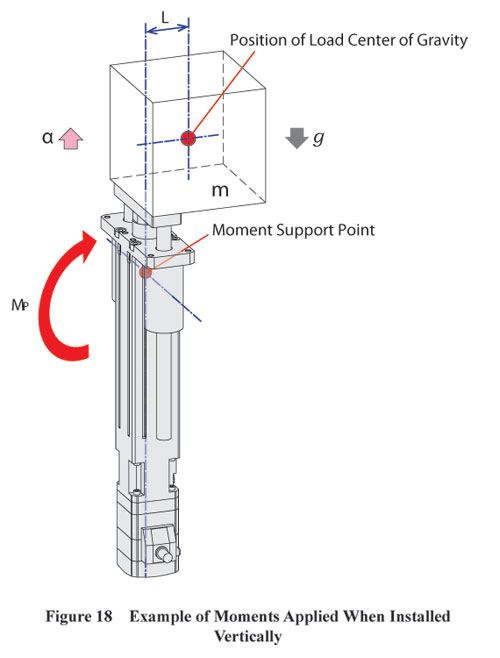
As shown in Figure 18, when indicating the pitching direction moment as Mp, which is applied to the vertically installed linear bush, it can be calculated with the following formula (6).
![]()
This is to confirm that the calculated value of the pitching direction moment is within the range of the dynamic permissible moment.
8.2.2. Transferring Loads in Horizontal Direction
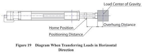
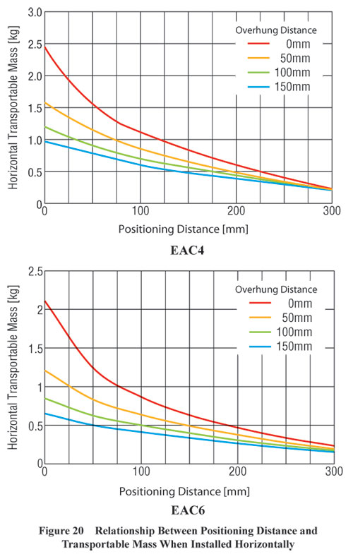
Next, with the cylinder with a shaft guide as shown in Figure 18, the home position is set when the rod is inserted all the way. Figure 19 shows the relationship between the positioning distance and the transportable mass when transferring the load in the horizontal direction.
The load in the horizontal direction has the load itself and also the self-weight of the cylinder rod and shaft guide. This is applied to the linear bush as the moment. These aspects are considered and included in the figure.
9. Summary
The concept and procedures of moment load calculation methods for electric linear actuators and cylinders were explained in this article. With the actual equipment, there are various kinds of equipment conditions and driving conditions for electric actuators and cylinders and thus, it is very difficult to explain all the operating conditions. Oriental Motor offers selection calculations based on the operating conditions. For further details, please contact the nearest Oriental Motor sales office.
Linear Actuators

Linear Actuators
Linear Slides
Compact Linear Actuators