Products
Solutions
Technical Information
Motor Sizing
Downloads
Contact Us
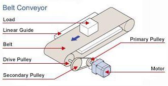
Motor Sizing Tools > Belt Conveyor
Belt Conveyor Sizing Tool
The following is the estimated requirements. Please contact 1-800-468-3982 ( from overseas 1-847-871-5931 ) for assistance or questions.
To print the calculation report, click
Full Report
To view the motor selection tips, click
Tips
 Print
Print
We're Here to Help
![]()
Business Hours:
Monday to Friday
8:30am EST to 5:00pm PST
Technical Support:
1-800-GO-VEXTA (468-3982)
Motor Sizing Services Available