Products
Solutions
Technical Information
Motor Sizing
Downloads
Contact Us
Speed Control Motors > CVK-SC Series Speed Control Stepper Motors
CVK-SC Series Speed Control Stepper Motors
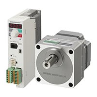
CVK-SC Series Speed Control Stepper Motors
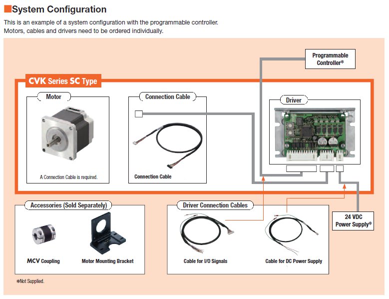
The CVK Series SC speed control system offers a simple configuration consisting of a stepper motor, driver and programmable controller. The operating speed, acceleration and deceleration time, running current can be set via the driver switches, and simply turning the FWD (RVS) input to ON or OFF allows for easy control.
- No pulse generator needed
- 2 speed settings are possible
- Compact and high torque stepper motor
- Improved stop position repeatability
- Maintains torque even when stopped
- Continuous duty is possible
- *Motor cables required (sold separately)
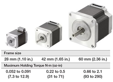
Speed Control Motor Lineup
Frame Size |
Power Supply |
Speed Control Range |
Max. Holding Torque |
|
|---|---|---|---|---|
|
24 VDC | 0.02 to 600 r/min |
7.3 ~ 12.9 oz-in |
0.052 ~ 0.091 N·m |
|
24 VDC |
0.02 to 600 r/min |
31 ~ 71 oz-in |
0.22 ~ 0.5 N·m |
|
24 VDC |
0.02 to 600 r/min |
93 ~ 290 oz-in |
0.66 ~ 2.1 N·m |
Speed Control Applications
The simple stepper motor and driver configuration makes speed control possible. Control is easy; select 2 speeds and turn the start input ON or OFF.
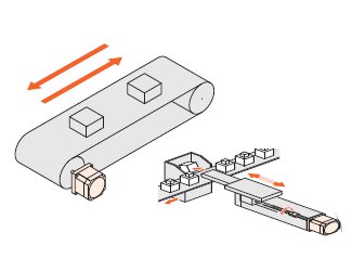
Regular Feed Operation
Turn the forward input ON or OFF
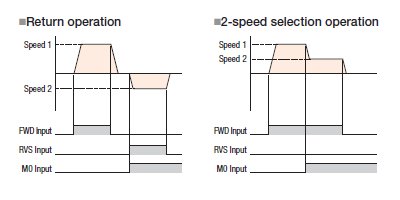
Return Operation
Turn the CW/CCW input ON or OFF
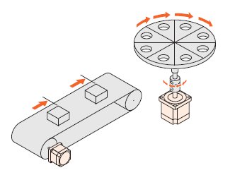
Speed Selection Operation
2-speed selection operation
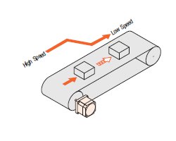
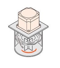
Smooth Low Speed Operation
Speed range is from 0.02 r/min to 600 r/min
Simple Speed Control
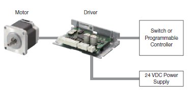
Simple System Configuration to Control I/O
Simple configuration consisting of stepper motor, driver and programmable controller. The operating speed, acceleration and deceleration time and running current can be set via the driver switches. Simply turning the FWD (RVS) input to ON or OFF allows for easy control.
2 Individual Speed Settings are Possible
The driver can be set to 2 individual speed and can be easily controlled externally.
Maintains Torque When Stopped
Motor current is supplied when stopped so torque is still generated. This provides load holding capability (holding force is 50% of max. holding torque).
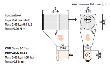
The Motor can be Downsized Thanks to the Use of Compact, High Torque Motors
Because a stepper motor provides high torque at low operation speeds it can be used without a gearhead. This allows for downsizing of the motor and decreasing the overall size of the equipment as compared to induction motors with almost identical speeds.
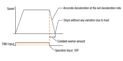
When the Operating Input is Constant Stop Position Reliability is Improved
When the motor is stopped, even if the load weight is changed, if the operating conditions are the same the deceleration traveling amount does not change due to inertial load or frictional load. This allows for improvement of the stop position repeatability.
Continuous Duty is Possible
For continuous duty, the below operating conditions are required and the motor case temperature needs to be less then or equal to 100°C (212°F).
When the ambient temperature is 50° C (122°F):
Driver P/N |
Motor P/N |
Condition for Motor |
Condition for Driver |
|
Max Driver Current Setting |
Needed Plate minimum size(mm) |
|||
CVD512B□-KSC |
PKP523N12□ |
100% |
175×175×6 |
Nothing |
PKP525N12□ |
100% |
|||
CVD518B□-KSC |
PKP543N18□2 |
100% |
200×200×6 |
|
PKP544N18□2 |
70% |
|||
PKP545N18□2 |
100% |
|||
PKP546N18□2 |
70% |
|||
CVD524B□-KSC |
PKP564FN24□2 |
100% |
350×350×6 |
When using the accessory, driver cover of PADC-CVD, the maximum operating current setting is at 70% |
PKP566FN24□2 |
100% |
|||
PKP569FN24□2 |
100% |
|||
When the ambient temperature is 40° C (104°F):
Driver P/N |
Motor P/N |
Condition for Motor |
Condition for Driver |
|
Max Driver Current Setting |
Needed Plate minimum size(mm) |
|||
CVD512B□-KSC |
PKP523N12□ |
100% |
175×175×6 |
Nothing |
PKP525N12□ |
100% |
|||
CVD518B□-KSC |
PKP543N18□2 |
100% |
200×200×6 |
|
PKP544N18□2 |
100% |
|||
PKP545N18□2 |
100% |
|||
PKP546N18□2 |
100% |
|||
CVD524B□-KSC |
PKP564FN24□2 |
100% |
350×350×6 |
When using the accessory, driver cover of PADC-CVD, the maximum operating current setting is at 70% |
PKP566FN24□2 |
100% |
|||
PKP569FN24□2 |
100% |
|||
Product Line
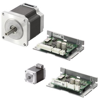
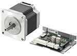
Motors
18 motor models in 3 frames sizes are available.
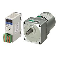
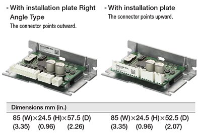
Driver
2 types of drivers are available.
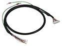
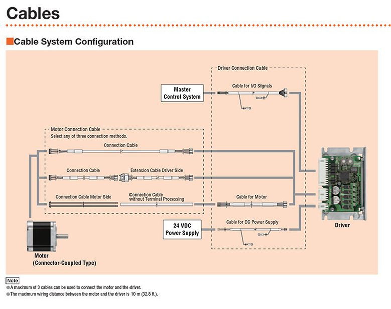
Motor Cables (*Required)
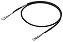
These cables are used to connect the connector-coupled motor with the driver. Because there are connectors on both sides the motor and driver can be connected directly.
Mounting Brackets
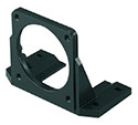
Mounting brackets are convenient for installation and securing a stepper motor or geared stepper motor.
Driver Cables (Optional)
These cables are used to connect the driver to I/O Signals, DC Power Supply and Motors (lead type).
Driver Mounting Bracket
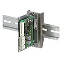
This is a DIN Rail mounting bracket for drivers with installation plates.
Driver Cover
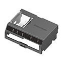
This cover provides protection for the driver and prevents accidental contact. For use with right-angle type connector type with installation plate.
External Resistor Module
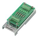
24 VDC output. This is a circuit for connecting the controller signal to the 5 VDC input driver. Module contains five sets of current limiting resistors (2.2 kΩ, 1/2 W) and LEDs.
System Configuration
CAD / Manual Search
To locate product CAD and Operator Manuals please search using the product Item Number.
Technical Articles
Videos
Brushless DC Speed Control Motors
AC Speed Control Motors