Stepper Motor Glossary of Terms
Angle Accuracy
The difference between the actual rotation angle and the theoretical rotation angle. Although there are several expressions according to how the criteria are set, generally, the angle accuracy of the stepper motor is expressed in terms of the stop position accuracy.
Angular Transmission Error
Angular transmission error is the difference between the theoretical rotation angle of the output shaft, as calculated from the input pulse number, and the actual rotation angle. It is generally observed when a reduction mechanism is provided. Angular transmission error is used to represent the accuracy of a reduction mechanism. Oriental Motor’s planetary (PN) gear is designed to minimize the angular transmission error to a maximum of only six arc minutes, and may be effectively used in high accuracy positioning and indexing applications.
Automatic Current Cutback
This is a function used for the automatic reduction of motor current by approximately 50% when the pulse signal is not input, in order to minimize the heating of the motor and driver. (Approximately 40% in CMK Series and UMK Series stepper motors). This function automatically reduces the motor current at motor standstill, and does so within approximately 0.1 second after the pulse signal stops.
![]()
Backlash
Backlash is a term used to describe the play in a gear or coupling. Since the range of backlash angle cannot be controlled, minimizing the backlash will help improve the accuracy of positioning. Oriental Motor provides the non-backlash harmonic and PN geared type as well as the TH geared type offering low backlash.
CW, CCW
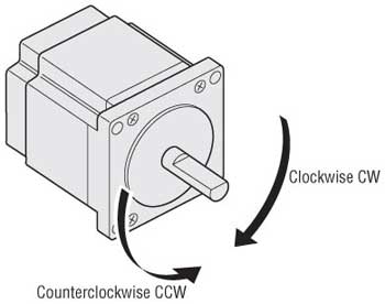
The rotation direction of a motor is expressed as CW (clockwise) or CCW (counterclockwise). These directions are as seen from the output shaft.

Excitation Home Position
The stepper motor rotates by sending current to the motor coils according to a preset combination and order. The excitation sequence is the order in which current is sent to the motor coils. It varies with the types of motor and excitation system.
Excitation Sequence
Condition in which the excitation sequence is in its initial condition. In the 5-phase stepper motor, the sequence returns to the initial condition at 7.2˚ intervals.
Gravitational Operation
Gravitational operation refers to the downward movement of a lifted load. Since the motor is operating by gravity, the servo motor used in this application generates electricity. To prevent damage to the driver as a result of the electricity thus generated, a regeneration circuit is required. The operation of stepper motors, including our , AlphaStep is synchronized with pulses, enabling speed control even during gravitational operation.
Inertial Load
This is the degree of force possessed by a physical object to maintain its current level of kinetic energy. Every physical object has an inherent inertial load. Greater torque is required to accelerate and decelerate an object having a larger inertial load. The degree of such torque is proportional to the degree of inertial load and the acceleration that is obtained from the operating speed and acceleration time.
Microstep
Microstepping is a technology used to achieve higher resolution by controlling the flow of current to the motor’s coil and dividing the step angle into smaller steps. Extremely small steps help eliminate vibrations caused by the stepping drive, thus achieving low vibration and low noise operation.
Misstep
Stepping motors are synchronized by pulse signals. They can lose their synchronization when speed changes rapidly or an overload occurs. Misstep is the term for losing synchronization with the input pulse. The correctly selected and normally operated motor doesn’t suffer a sudden misstep. Essentially, misstep is a condition in which an overload alarm occurs with a servo motor.
Overhung Load
The load on the motor shaft in the vertical direction. The value varies with the model.
Photocoupler
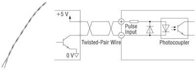
Photocouplers are electronic components that relay electrical signals as light. They are electronically insulated on the input and output sides, so noise has little effect on them. Input (output) "ON" indicates that the current is sent into the photocoupler (transistor) inside the driver. Input (output) "OFF" indicates that the current is not sent into the photocoupler (transistor) inside the driver.
![]()
Pulse Input Mode
The pulse mode used when the CW/CCW rotation direction is controlled by the pulse command. The pulse input configuration may be 1-pulse (1P) input mode or 2-pulse (2P) input mode. The 1-pulse input mode uses the pulse signal and rotation direction signal, while the 2-pulse input mode uses the CW pulse input for the CW direction and the CCW pulse input for the CCW direction.
Resonance
This refers to the phenomenon in which vibration becomes larger at specific speeds. Resonance is a result of the characteristic vibration frequency and operating vibration of a motor or other mechanism. For 2-phase stepper motors, there are resonance areas between 100 Hz and 200 Hz; 5-phase stepper motors have lower levels of resonance.
Thrust Load
The thrust load is the load in the direction of the motor output shaft. The value varies with the model.
Twisted-Pair Wire
Twisted-pair wires entwine two wires as shown in the figure below. They are used to reduce noise in signal wires. Because the wires face in opposite directions from each other and carry the same current, noise from the ambient surroundings is canceled out and noise effects reduced.


