Products
Solutions
Technical Information
Motor Sizing
Downloads
Contact Us
AC Motors & Gear Motors > Technology > AC Motor Overview
AC Motor Overview
Structure of Standard AC Motors
The following figure shows the construction of a standard AC motor.
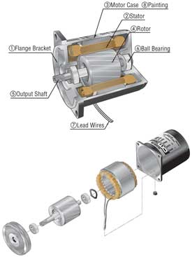
1. Flange Bracket Die cast aluminum bracket with a machined finish, press-fitted into the motor case
2. Stator Comprised of a stator core made from electromagnetic steel plates, a polyester-coated copper coil and insulation film
3. Motor case Die cast aluminum with a machined finish inside
4. Rotor Electromagnetic steel plates with die cast aluminum
5. Output shaft Available in round shaft type and pinion shaft type. The metal used in the shaft is S45C. Round shaft type has a shaft flat (output power of 25 W 1/30 HP or more), while pinion shaft type undergoes precision gear finishing.
6. Ball bearing
7. Lead wires Lead wires with heat-resistant polyethylene coating
8. Painting Baked finish of acrylic resin or melamine resin
Brake Mechanism of Reversible Motors
A reversible motor has a built-in friction brake mechanism (friction brake) at its rear. This mechanism is provided for the following purposes:
- To improve the instant reversing characteristics by adding a friction load
- To reduce overrun
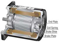
The brake mechanism is constructed as shown in the figure above. The coil spring applies constant pressure to allow the brake shoe to slide toward the brake plate. This mechanism provides a certain degree of holding brake force, but the force is limited due to the mechanism's structure, as described above. The brake force produced by the brake mechanism of an Oriental Motor reversible motor is approximately 10% of the motor's output torque.
Structure of an Electromagnetic Brake
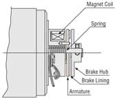
An electromagnetic brake motor is equipped with a power-off activated type electromagnetic brake. As shown in the figure, when voltage is applied to the magnet coil, the armature is attracted to the electromagnet against the force of the spring, thereby releasing the brake and allowing the motor shaft to rotate freely. When no voltage is applied, the spring works to press the armature onto the brake hub and hold the motor's shaft in place, thereby actuating the brake.
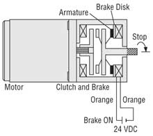
Structure & Operation of a CB Motor
The illustration to the right shows the structure of the C·B motor. When 24 VDC is not applied to either the clutch coil or brake coil, the output shaft can be rotated freely.
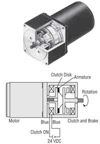
- Operation: When 24 VDC is applied to the clutch coil, the armature of the clutch coil is drawn against the clutch disk, transmitting motor rotation to the output shaft. The motor continues to rotate.
- Stopping & Load Holding: By removing the clutch coil excitation, after a certain time lag, applying 24 VDC to the brake coil will cause the armature on the brake to come into contact with the brake disk, which will cause the output shaft to come to a stop. During braking, the output shaft is released from the motor, so the inertia from the motor has no effect. The motor is constantly rotating.
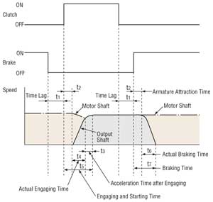
The figure below shows the relationship between the action of the motor shaft and output shaft and the state of excitation of the clutch and brake coils.
Operation
When operation is shifted from holding the load to moving the load, a time lag of 20 ms or more is required after releasing the brake and before applying voltage to the clutch (this is to prevent the clutch and brake from engaging at the same time). The time required for the clutch/brake output shaft to reach a constant speed after applying voltage to the clutch is referred to as the engaging and starting time (t5) and is calculated by adding up the following time elements:
1. Armature Attraction Time t2 The time required for the armature to come into contact with the clutch after voltage application to the clutch.
2. Actual Engaging Time t4 The time required for the clutch/brake output shaft, which is accelerated by dynamic friction torque, to engage completely with the motor shaft after the armature comes in contact with the clutch.
3. Acceleration Time after Engaging t3 The time needed to accelerate to the required speed when load is suddenly applied to the motor during actual engaging time described in (2), causing a temporary drop in speed.
Braking
When operation is shifted from rotation to stopping or holding a load, a time lag of 20ms or more is required after releasing the clutch and before applying voltage to the brake. The time required for the clutch/brake output shaft to come to a stop after applying voltage to the brake is referred to as the braking time (t7) and is calculated by adding up the following time elements:
1. Armature Attraction Time t2 The time required for the armature to contact with the brake plate after voltage application to the brake.
2. Actual Braking Time t6 The time required for rotation of the clutch/brake output shaft to come to a stop after the armature comes into contact with the brake plate.
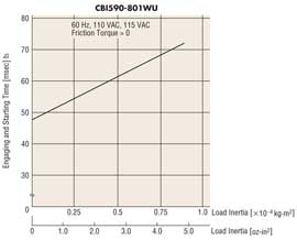
Engaging and Starting Characteristics (Reference value):
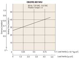
Braking Characteristics (Reference value):
Speed-Torque Characteristics of Induction Motors
The figure below shows the speed – torque characteristics of induction motors.
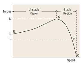
Under no load, the motor rotates at a speed close to synchronous speed. As the load increases, the motor's speed drops to a level (P) where a balance is achieved between load and motor torque (Tp). If the load is further increased and reaches point M, the motor can generate no greater torque and stops at point R.
In other words, the motor can be operated in a stable range between M and O, while the range between R and M is subject to instability.
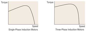
Induction motors are available in two types: single-phase (capacitor run) and three-phase induction motors. With the single-phase motor, the starting torque is generally smaller than the operating torque, while the three-phase motor features a relatively greater starting torque.
The torque the motor produces changes proportionally to roughly twice the power supply voltage.
For example, if 110 V is applied to a motor whose rated voltage is 100 V, the torque produced by the motor increases to approximately 120%. In this case, the motor temperature will rise and may exceed the permissible range.
If 90 V is applied to the same motor, the torque produced by the motor decreases to approximately 80%. In this case, the motor may not be able to operate the automated equipment as expected.
For the above reasons, the power supply voltage should be kept within ±10% of the rated voltage. Otherwise, when the power supply voltage fluctuates beyond the aforementioned range, the motor temperature may rise beyond the permissible range or the motor torque may drop and thereby make the equipment operation unstable.
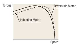
Speed-Torque Characteristics of Reversible Motors
The reversible motor is a capacitor run, single-phase induction motor that features the same speed – torque characteristics as an induction motor, as described above. However, the reversible motor features a higher starting torque than an induction motor in order to improve the instant reversing characteristics.
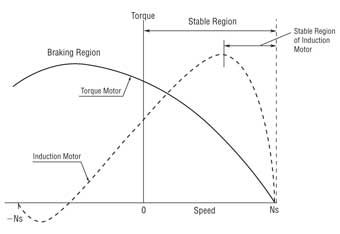
Speed-Torque Characteristics of Torque Motors
The figure below shows the speed – torque characteristics of torque motors. The speed – torque characteristics of torque motors differ from those of induction motors or reversible motors. As the graph shows, they have sloping characteristics (torque is highest at zero speed and decreases steadily with increasing speed), enabling stable operation over a wide speed range, from starting to no load speed.
The torque generated during reversal of the motor is a large positive torque in the same direction as the rotational magnetic field. When the motor which rotates uni-directionally is locked by the load and the motor is rotated opposite the desired direction, this torque acts as a force (braking force) to inhibit the motor from rotating backwards.
Temperature Rise in Standard AC Motors
Temperature Rise in Motors
When a motor is operating, all energy loss (copper loss, iron loss, etc.) of the motor is transformed into heat, causing the motor's temperature to rise.
- Induction motors (continuous rating) reach the saturation point of temperature rise after two or three hours of operation, whereupon its temperature stabilizes.
- Reversible motors (30 minutes rating) reach their limit for temperature rise after 30 minutes of operation. The temperature will increase further if operation continues.
Measuring the Temperature Rise
The following is a description of the methods Oriental Motor uses for temperature measurement and for the determination of a motor's maximum permissible temperature rise.
- Thermometer Method
The temperature at which the temperature rise during motor operation becomes saturated is measured using a thermometer or thermocouple attached to the center of the motor case. The temperature rise is defined as the difference between the ambient temperature and measured temperature.
- Resistance Change Method
In the resistance change method, the winding temperature is measured according to the change in resistance value. A resistance meter and thermostat is used to measure the motor's winding resistance and ambient temperature before and after operation, from which the temperature rise in the motor windings is obtained.
Operating Time & Temperature Rise - Reversible Motors
Reversible motors have a “30 minute rating”. However, the operating time varies according to the operating conditions, even with intermittent operation for short times. When using a reversible motor intermittently for a short period of time a large current flows, which causes a large amount of heat generation when starting or reversing. However, as the natural cooling effect of the motor is high when the motor is left stopped for a longer period of time, you can curb rises in temperature.
The motor case temperature equals the rise in motor temperature plus the ambient temperature. Generally, if the case temperature of the motor is 90˚C (194˚F) or less, continuous motor operation is possible with the same operating conditions, considering the insulation class of motor winding. However, the lower the motor temperature is, the longer the bearing grease life is. The motor temperature varies according to conditions such as the load, the operating cycle, the mounting method of the motor and the ambient temperature.
Overheat Protection Device
If a motor operating in run mode locks due to overload, ambient temperature rises rapidly, or the input current increases for some reason, the motor's temperature rises abruptly. If the motor is left in this state, the performance of the insulation within the motor may deteriorate, reducing its life and in extreme cases, scorching the winding and cause a fire. In order to protect the motor from such thermal abnormalities, our motors recognized by UL and CSA Standards and conform to EN and IEC Standards are equipped with the following overheat protection device.
Thermally Protected Motors
Motors with a frame size of 70 mm (2.76 in.) sq., 80 mm (3.15 in.) sq., 90 mm (3.54 in.) sq., or 104 mm (4.09 in.) sq. contain a built-in automatic return type thermal protector. The structure of a thermal protector is shown in the figure below.
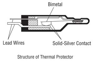
The thermal protectors employ bimetal contacts, with solid silver used in the contacts. Solid silver has the lowest electrical resistance of all materials, along with a thermal conductivity second only to copper.
◇ Operating Temperature of Thermal Protector
Open··· 130±5˚C (266±9˚F)
[the operating temperature varies depending on the model,
e.g., BH Series: 150±5˚C (302±9˚F)]
Close··· 82±15˚C (179.6±27˚F)
[the operating temperature varies depending on the model,
e.g., BH Series: 96±15˚C (204.8±27˚F)]
The motor winding temperature, where the thermal protector is activated, is slightly higher than the operating temperature listed above.
Impedance Protected Motors
Motors with a frame size of 60 mm (2.36 in.) sq. or less are equipped with impedance protection. Impedance protected motors are designed with higher impedance in the motor windings so that even if the motor locks, the increase in current (input) will be minimized and temperature will not rise above a certain level.
Capacitor
Oriental Motor's single-phase AC motors are all permanent split capacitor types. Permanent split capacitor motors contain an auxiliary winding offset by 90 electrical degrees from the main winding. The capacitor is connected in series with the auxiliary winding, causing the advance of current phase in the auxiliary winding.
Motors employ vapor-deposition electrode capacitors recognized by UL. This type of capacitor, which uses a metalized paper or plastic film as an element, is also known as a “self-healing (SH) capacitor” because of the self-healing property of the capacitor element.
Although most of the previous capacitors used paper elements, the plastic film capacitor has become a mainstream model in recent years due to the growing demand for compact design.
- Capacitance: The use of a capacitor with a different capacitance may cause excessive motor vibration and heat generation or may result in torque drops and unstable operation. Be sure to use the capacitor included with the motor. The capacitor's capacitance is expressed in microfarads (μF).
- Rated Voltage: Using a capacitor exceeding the rated voltage may cause damage, smoke or ignition. Be sure to use the capacitor included with the motor. The rated voltage of the capacitor is expressed in volts (V). The capacitor’s rated voltage is indicated on the surface of the capacitor case. Take proper precautions, since the capacitor’s rated voltage is different from that of the motor.
- Rated Conduction Time: The rated conduction time is the minimum design life of the capacitor when operated at the rated load, rated voltage, rated temperature and rated frequency. The standard life expectancy is 25,000 hours. A capacitor that breaks at the end of its life expectancy may smoke or ignite. We recommend that the capacitor be replaced after the rated conduction time. Consider providing a separate protection measure to prevent the equipment from being negatively influenced in the event of capacitor failure.
- Safety Feature of Capacitor: Some capacitors are equipped with a safety feature that allows for safe and complete removal of the capacitor from circuits to prevent smoke and/or fire in the event of a dielectric breakdown. Oriental Motor products use capacitors with UL recognized safety features that have passed the UL 810 requirement of the 10000 A fault current test.
Single-Phase Gear Motors
Three-Phase Gear Motors