Products
Solutions
Technical Information
Motor Sizing
Downloads
Contact Us
Stepper Motors > Stepper Motor Only > αSTEP Closed Loop Stepper Motors > AZ Series Connector Type Stepper Motors
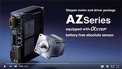
AZ Series Closed Loop, Absolute Stepper Motors
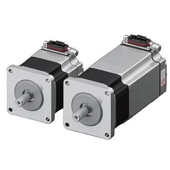
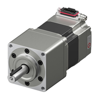
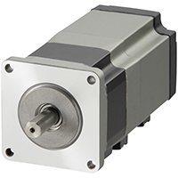
AZ Series Connector Type Stepper Motors
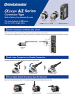
Connector type motor has been added to the αSTEP AZ Series. One cable, IP66 rated locking connector enables a simple, direct connection between the motor and the driver. Available in three cable outlet directions: output shaft side, vertical and opposite output shaft side.
Current motor cable connections not compatible with Multi-Axis Drivers.
- Battery-Free, Mechanical Absolute Encoder
- Closed Loop Performance, No Hunting or Gain Tuning
- AC or DC Input Types
- Electromagnetic Brake Type Available
- αSTEP AZ Series Stepper Motor Driver Required*
Stepper Motor Lineup
Connector Type |
Frame Size |
Driver Power Input |
Motor Types |
Available Options |
Max. Holding Torque |
|
|---|---|---|---|---|---|---|
|
1.65 in. (42 mm) NEMA 17 Stepper Motors |
AC Input | Standard Type |
Electromagnetic Brake
|
42 ~ 109 oz-in |
0.3 ~ 0.77 N·m |
Geared Type |
92 ~ 1558 oz-in |
0.65 ~ 11 N·m |
||||
| DC Input | Standard Type |
42 ~ 102 oz-in |
0.3 ~ 0.72 N·m |
|||
Geared Type |
92 ~ oz-in |
0.65 ~ N·m |
||||
| 2.36 in. (60 mm) NEMA 24 Stepper Motors |
AC Input | Standard Type |
142 ~ 280 oz-in |
1 ~ 2 N·m |
||
Geared Type |
254 ~ 5098 oz-in |
1.8 ~ 36 N·m |
||||
| DC Input | Standard Type |
142 ~ 280 oz-in |
1 ~ 2 N·m |
|||
Geared Type |
254 ~ 5098 oz-in |
1.8 ~ 36 N·m |
||||
3.35 in./3.54in. (85/90 mm) |
AC Input |
Standard Type |
280 ~ 566.4 oz-in |
2 ~ 4 N·m |
||
Geared Type |
848 ~ 15152 oz-in |
6 ~ 107 N·m |
||||
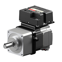
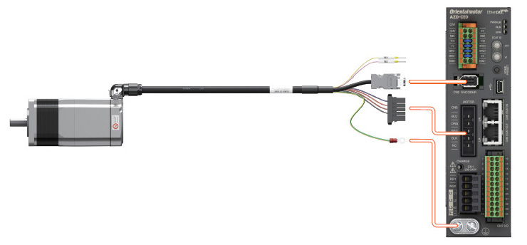
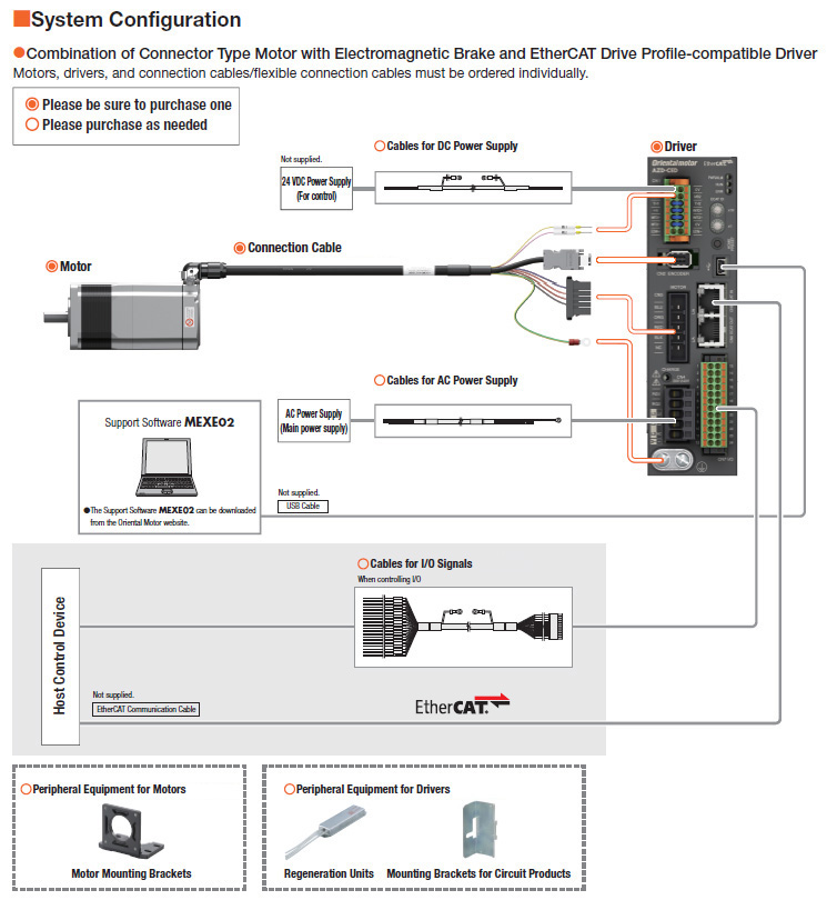
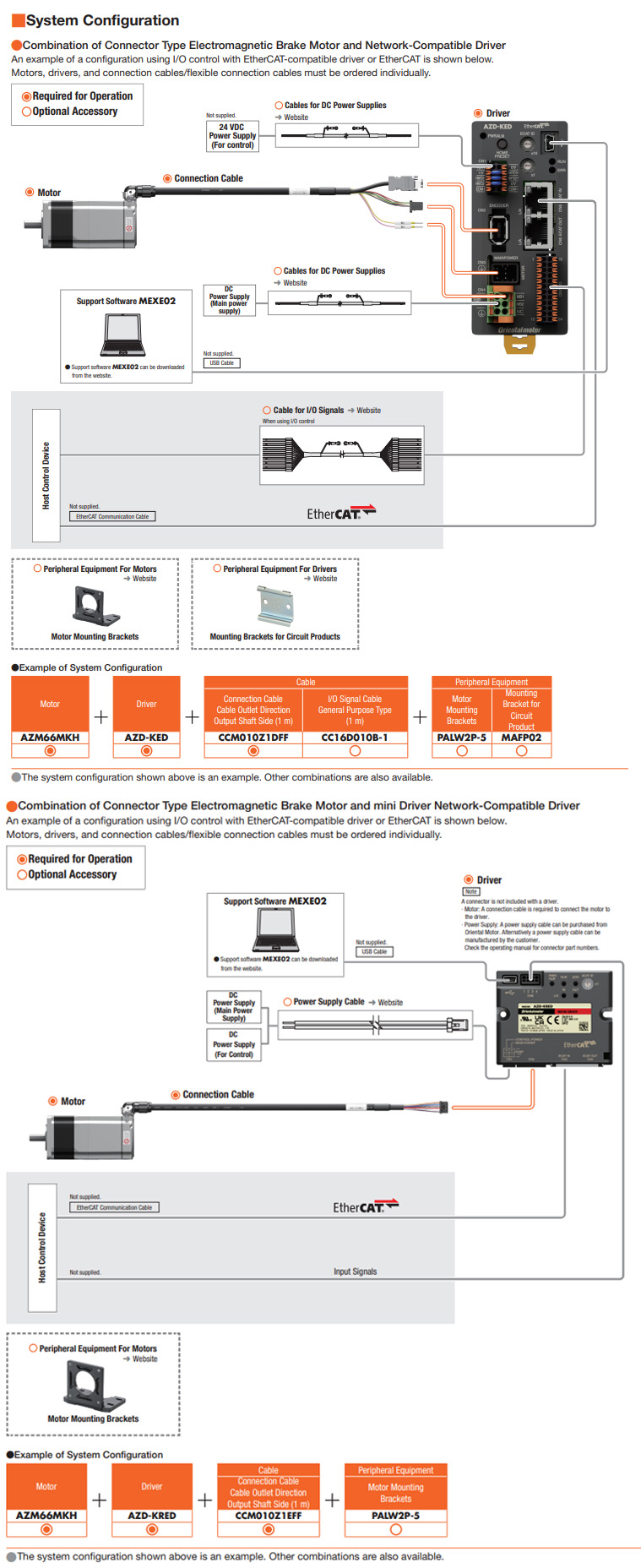
Connector Type

Direct Connection Motor to Driver
One cable locking connector allows for a maximum of 10 m (32.8 ft.) between the motor and driver with the same motor performance specifications as our standard AZ Series.
Current motor cable connections not compatible with AZ Mini DC or Multi-Axis Drivers.
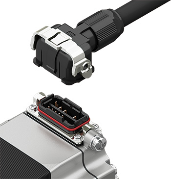
The one motor and driver cable includes the power line to the motor, signal line, electromagnetic brake line (brake motor type) and the ground wire for easy motor connection with no separate connection required for extension cables.
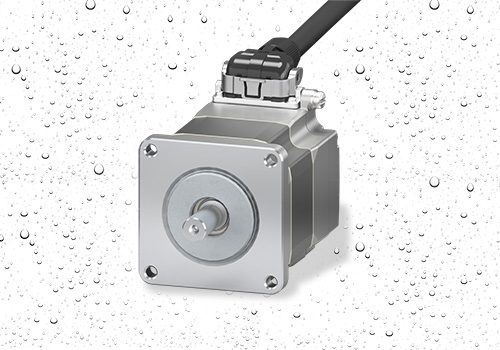
Degree of Protection IP66
With the degree of protection IP66, it is highly dustproof and can be used in environments where it may be exposed to water droplets.
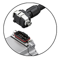
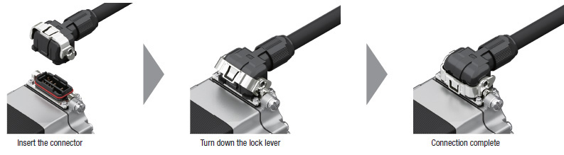
A Lock Lever Connector is Used To Ensure Connection
Connecting the cable is easy due to the lock lever that does not require screws.
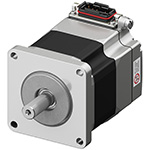
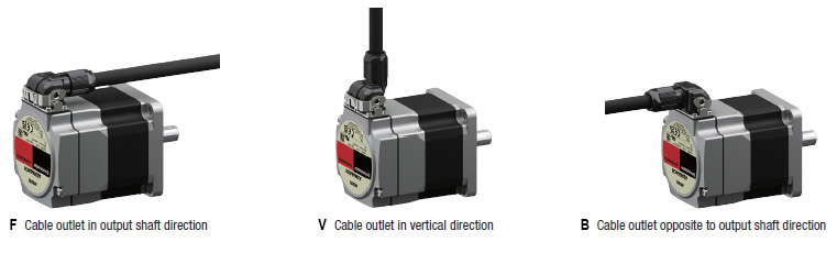
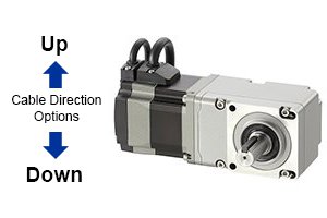
Three Cable Outlet Directions Can be Selected
The product line contains multiple cable outlet directions. This allows for choosing the cable type based on the cable outlet direction required.
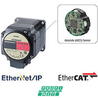
Mechanical Type Absolute Encoder
Advanced Technology at Affordable Prices
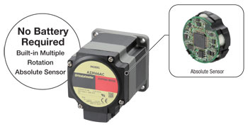
Oriental Motor has developed and patented a compact, low-cost, battery-free mechanical type absolute sensor. The αSTEP AZ Series is available at affordable prices and can contribute to improved productivity and cost reductions.
Mechanical-Type Encoder (No Battery Required)
A mechanical sensor composed of multiple gears is employed. Positioning information is detected by recognizing the angle of the individual gears. As a result, it does not require a battery.
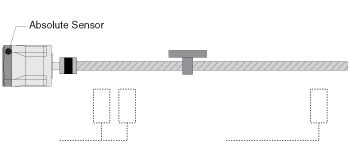
Multiple-Rotation Absolute System*
Absolute position detection is possible with ±900 rotations (1800 rotations) of the motor shaft from the home position.
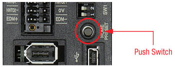
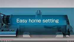
Home Setting Method*
The home position can be easily set by pressing a switch on the drivers surface, which is saved by the Mechanical Absolute Encoder. In addition, home setting is possible with the MEXE02 data setting software or external input signal.
Home position is easy to adjust by moving the motor to a desired position manually.
*Requires AZ Series Driver
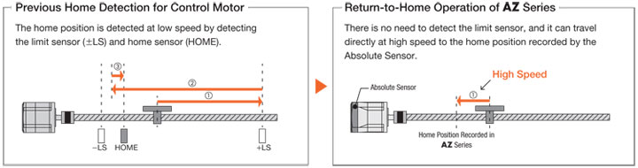
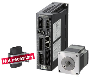
No External Sensors Required
Positional information is managed mechanically. External sensors such as home sensor and the limit sensor are not needed.
Reduced Cost
Sensor costs and wiring costs can be reduced, allowing for lower system costs.
Simple Wiring
Wiring is simplified and the degree of freedom for equipment design is increased.
Not Affected by Sensor Malfunctions
There is no concern about sensor malfunctions (when operating in environments filled with oil mist or filled with metal pieces due to metal processing), sensor failures or sensor wire disconnections.
Improved Return-to-Home Accuracy
Home position accuracy is increase because the return-to-home operation is performed regardless of any variations in home sensor sensitivity.
Shortened Reset Time - High Speed Return-to-Home
Because return-to-home is possible without an external sensor, return-to-home can be performed at high speed without taking the sensor sensitivity into account, allowing for a shortened machine cycle.
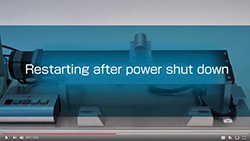
No Battery Required
No battery is required thanks to a mechanical-type sensor. Because positioning information is managed mechanically by the Mechanical Absolute Encoder, the positioning information can be preserved, even if the power turns off, or the cable between the motor and the driver is disconnected.
Reduced Maintenance
Because there is no battery that needs replacement, maintenance time and costs can be reduced.
Unlimited Driver Installation Possibilities
Because there is no need to secure space for battery replacement, there are no restrictions on the installation location of the driver, improving the flexibility and freedom of the layout design of the control box.
Safe for Overseas Shipping
Normal batteries will self-discharge, so care must be taken when the equipment requires a long shipping time, such as when being sent overseas. The Mechanical Absolute Encoder does not require a battery, so there is no limit to how long the positioning information is maintained. In addition, there is no need to worry about various safety regulations, which must be taken into consideration when shipping a battery overseas.
Position Holding Even when the Cable between the Motor and Driver is Detached
Positioning information is stored within the Mechanical Absolute Encoder.
*Because the positioning information is stored in the Mechanical Absolute Encoder, the home position must be reset if the motor is replaced.
High Reliability
High Reliability is provided by using the control method unique to Oriental Motor that combines the merits of both open loop control and closed loop control.
Continues Operation Even with Sudden Load Fluctuation and Sudden Acceleration
In normal conditions, it operates synchronously with pulse commands under open loop control, and because of its compact size and high torque generation, it has excellent acceleration performance and response. In an overload condition, it switches immediately to closed loop control to correct the position.
Alarm Signal Output in Case of Abnormality
If a continuous overload is applied, an alarm signal is output. Also, when the positioning is completed, a signal is output. This provides high reliability.
No Tuning Required
Because it is normally operated with open loop control, positioning is still possible without gain tuning even when the load fluctuates due to the use of a belt mechanism, cam or chain drive, etc.
Holding the Stop Position
During positioning, the motor stops with its own holding force without hunting. Because of this, it is ideal for applications where the low rigidity of the mechanism requires absence of vibration upon stopping.
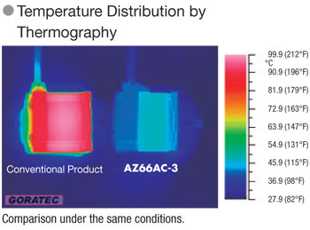
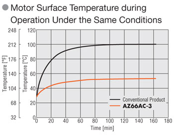
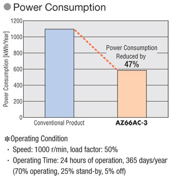
Energy Saving
Heat generation is reduced thanks to the high efficiency motor, resulting in energy savings.
Lower Heat Generation
Heat generation by the motor has been significantly reduced through higher efficiency.
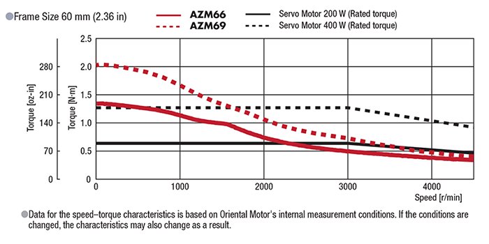
αSTEP Performance
What is the Output of αSTEP?
"Rated Output" is not listed because αSTEP has no "rated speed". Refer to the graph below to compare rate torque of the αSTEP to Watts of of servo motor's rated output torque.
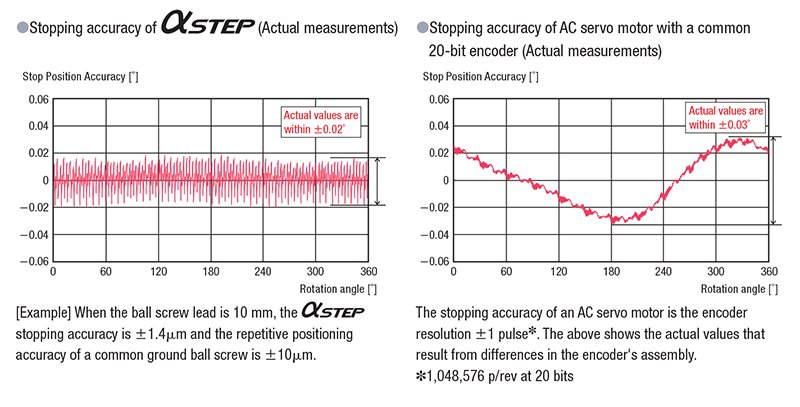
What is the Stopping Accuracy of αSTEP?
The stopping accuracy of a typical αSTEP is ±0.05° (under no load), which is equivalent to that of servo motors. The graphs below show the actual measured stopping accuracies when an αSTEP and an AC servo motor were rotated once.
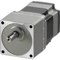
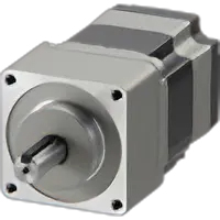
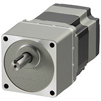
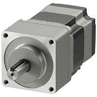
Standard Type Stepper Motors
The standard type AZ Series stepper motors are available in 3 output shaft types; Round Shaft*, Round Shaft with Flat and Key Shaft*.
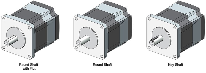
*Round Shaft and Key Shaft only available on 1.65 in. (42 mm), 2.36 in. (60 mm) and 3.35 in. (85 mm) sizes.
Geared Type Types and Features
Type |
Features |
Frame Size [mm] |
Backlash [arcmin] |
Lost Motion [arcmin] |
Gear Ratio |
Speed Control Range [r/min] |
||
|---|---|---|---|---|---|---|---|---|
Low Backlash |
|
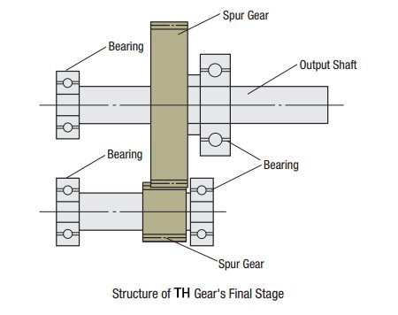
TS Geared (Spur gear mechanism) |
High-speed operation |
42~90 |
10~45 |
- |
3.6~30 |
0~833 |
|
Right-Angle Shaft FC Geared (Face gear mechanism) |
Space saving |
35, 42, 60 |
10~25 |
- |
7.2~30 |
0~416 |
|
|
PS Geared (Planetary gear mechanism) |
High torque |
28~90 |
7~35 |
- |
5~50 |
0~600 |
|
Non-Backlash |
|
PN Geared (Planetary gear mechanism), HPG Geared (Harmonic Planetary®) |
High-speed operation High torque High accuracy |
28~90 |
PN geared: 0 HPG geared: 3 |
3 |
5~15 |
0~900 |
|
Harmonic Geared (Harmonic Drive®) |
Low speed operation High torque High accuracy |
30~90 |
- |
1.5 |
50, 100 |
0~70 |
|
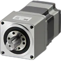
Taper Hobbed Gear Stepper Motors (TS)
- 1.65 in. (42 mm)
- 2.36 in. (60 mm)
- 3.54 in. (90 mm)
High Speed, Low Backlash Gears
This geared type is made with a simple spur gear design. The torque and speed have been improved.
Because of its high accuracy, this type has the same level of accuracy when compared to our tapered (TH) type without the added cost of tapering.
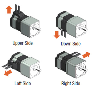
Cable outlet direction can be selected
There is a choice of four cable outlet directions in relation to the output shaft. Please contact technical support for the details.
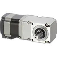
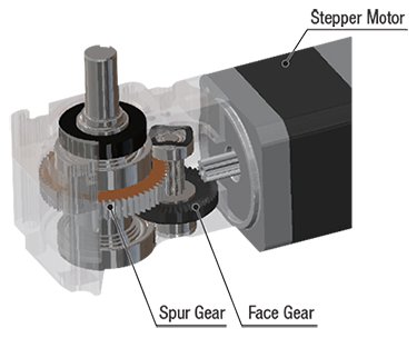
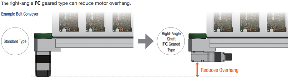
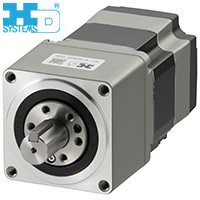
Right-Angle Face / Spur Gear (FC)
- 1.38 in. (35 mm)
- 1.65 in. (42 mm)
- 2.36 in. (60 mm)
The right-angle FC geared type is a compact orthogonal shaft geared motor made up of a disc-shaped gear (face gear) meshing with a spur gear. By combining it with an AZ series motor, high precision, high strength and space savings is possible at an affordable price.
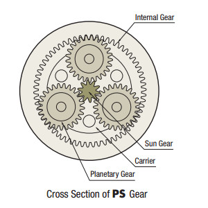
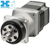
Planetary Gear Stepper Motors (PS)
- 1.10 in. (28 mm)
- 1.65 in. (42 mm)
- 2.36 in. (60 mm)
- 3.54 in. (90 mm)
High Torque, Low Backlash Gears
The PS gear mechanism is comprised primarily of a sun gear, planetary gears and an internal tooth gear. The planetary gears design allow for higher output torque.
There are gears inside used to distribute torque, which allows for higher torque than a spur gear design. The PS gear uses a higher accuracy gear design which provides for a lower backlash when compared to a spur gear design.
Planetary Gear, Non-Backlash, Stepper Motors (PN)
- 1.10 in. (28 mm)
- 1.65 in. (42 mm)
- 2.36 in. (60 mm)
High Accuracy, Non-Backlash Gears
PN Gears offers zero backlash and high precision in a compact design. By adding low gear ratio models, they support high-speed applications that harmonic gears can't handle.
Neugart High Torque Planetary Gear Stepper Motor (PLE)
- 1.65 in. (42 mm)
- 2.36 in. (60 mm)
- 3.54 in. (90 mm)
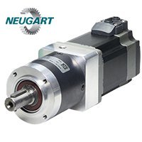
Higher Torque, Lower Backlash Gears
The PLE Series gearhead employs optimized planetary gear mechanism and is composed of fully hardened gears. Sun gear and planetary gears are honed (precision final machining after heat treatment). This technology guarantees extremely high torque density, long life, low backlash, and so on.
*Motor and Gearhead ship separately and must be assembled using the included gasket and screws
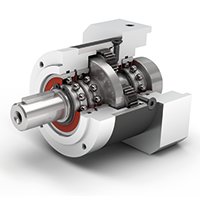
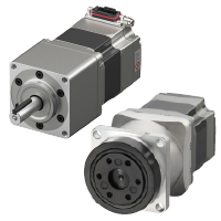
Harmonic Planetary Gear Stepper Motors (HPG)
- 1.65 in. (42 mm)
- 2.36 in. (60 mm)
- 3.54 in. (90 mm)
High Accuracy, Non-backlash Gears
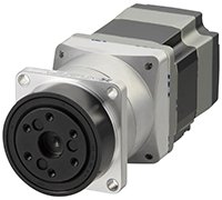
The HPG gear combine a harmonic and planetary gear speed-reduction mechanism allowing for high positioning accuracy, high permissible torque and high maximum instantaneous torque. The HPG Gears are available with a center shaft or surface mount to meet the needs of various applications.
Harmonic Gear Stepper Motors (HS)
- 1.18 in. (30 mm)
- 1.65 in. (42 mm)
- 2.36 in. (60 mm)
- 3.54 in. (90 mm)
High Accuracy, Non-Backlash Performance Gears
The mechanical life, permissible torque and maximum torque are improved (compared with conventional models).
Improved Rate Life (Twice the length of conventional models)
The rate life has been increased from 5,000 hours (conventional model) to 10,000 hours.
[Except for 1.65 in. (42 mm) frame size]
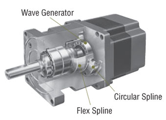
The harmonic gear utilizes the metal’s electrodynamics property. It is comprised of three basic components, a wave generator, flex spline and circular spline.
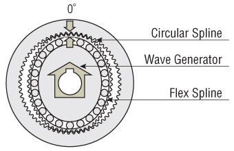
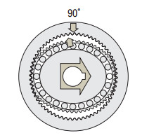
Rotating the wave generator (input) clockwise while keeping the circular spline fixed in position will subject the flax spline to elastic deformation, causing a gradual shift in the point of engagement between the circular spline and flex spline.
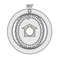
When the wave generator completes one revolution, the flex spline has rotated two fewer teeth than the circular spline has, resulting in the movement of the flex spline for the difference in the tooth count (two teeth) in the opposite direction of the wave generator's rotation (i.e. counterclockwise). This movement translates into output, thereby reducing the speed.
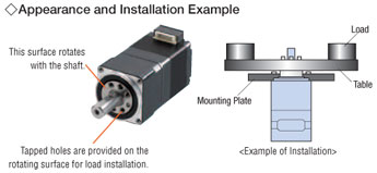
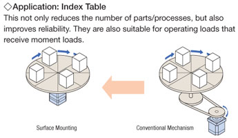
Surface Installation of Load
The harmonic geared type permits installation of load directly on the rotating surface integrated with the shaft. [Expect for geared stepper motors with a frame size of 3.54 in. (90 mm)].
Electromagnetic Brake Option
- 1.65 in. (42 mm)
- 2.36 in. (60 mm)
- 3.35 / 3.54 in. (85 / 90 mm)
These products have built-in power-off activated electromagnetic brakes. When power is accidentally cut off due to a blackout or other unexpected events, the electromagnetic brake holds the load in position to prevent it from dropping or moving. Also, when the motor is at standstill, it can be held by the electromagnetic brake. It is possible to suppress the heat generated from the motor by turning off the motor current.
CAD / Manual Search
To locate product CAD and Operator Manuals please search using the product Item Number.
Downloads
Videos
Technical Articles
Reference
Videos
Product Brochure
αStep AZ Series Product Family
Mounting Bracket for AZ mini Driver