Products
Solutions
Technical Information
Motor Sizing
Downloads
Contact Us
AC Motors & Gear Motors > Constant Speed AC Motors > Induction Motors
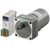
AC Induction Motors & Gear Motors
Single-Phase AC Induction Motors & Gear Motors
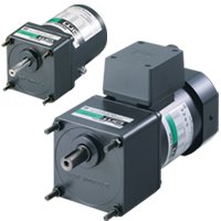
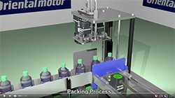
AC induction motors are optimal for uni-directional and continuous operation such as a conveyor system. All you need is to connect a capacitor and plug the motor into an AC power supply and the motor can be easily operated.
- 1 W (1/750 HP) up to 200 W (1/4 HP)
- Parallel Shaft, Right-Angle Solid Shaft, Right-Angle Hollow Shaft Gear Motors
- Stainless Steel Output Shafts available
- Round Shaft (no Gear) Types
- Electromagnetic Brake Available
- Single-Phase 110/115 VAC or Single-Phase 220-230 VAC
Three-Phase AC Induction Motors & Gear Motors
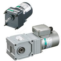
AC induction motors are optimal for uni-directional and continuous operation such as a conveyor system. All you need is to plug the motor into an AC power supply and the motor can be easily operated.
- 6 W (1/125 HP) up to 200 W (1/4 HP)
- Parallel Shaft, Right-Angle Solid Shaft, Right-Angle Hollow Shaft Gear Motors
- Round Shaft (no Gear) Types
- Electromagnetic Brake Available
- Three-Phase 200-230 VAC or Three-Phase 208/230/460 VAC
- Inverters sold separately
AC Induction Motors & Gear Motors
The following figure shows the construction of an AC induction motor.
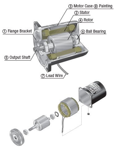
1. Flange Bracket Die cast aluminum bracket with a machined finish, press-fitted into the motor case
2. Stator Comprised of a stator core made from electromagnetic steel plates, a polyester-coated copper coil and insulation film
3. Motor case Die cast aluminum with a machined finish inside
4. Rotor Electromagnetic steel plates with die cast aluminum
5. Output shaft Available in round shaft type and pinion shaft type. The metal used in the shaft is S45C. Round shaft type has a shaft flat (output power of 25 W 1/30 HP or more), while pinion shaft type undergoes precision gear finishing.
6. Ball bearing
7. Lead wires Lead wires with heat-resistant polyethylene coating
8. Painting Baked finish of acrylic resin or melamine resin
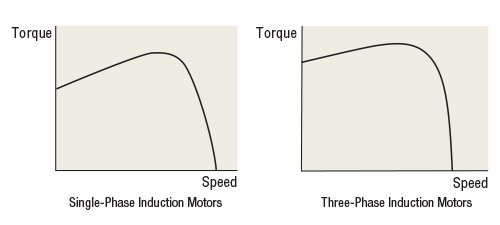
Speed - Torque Characteristics of Induction Motors
The figure below shows the speed – torque characteristics of induction motors.
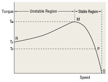
Under no load, the motor rotates at a speed close to synchronous speed. As the load increases, the motor's speed drops to a level (P) where a balance is achieved between load and motor torque (Tp). If the load is further increased and reaches point M, the motor can generate no greater torque and stops at point R. In other words, the motor can be operated in a stable range between M and O, while the range between R and M is subject to instability.
Induction motors are available in two types: single-phase (capacitor run) and three-phase induction motors. With the single-phase motor, the starting torque is generally smaller than the operating torque, while the three-phase motor features a relatively greater starting torque.
The torque the motor produces changes proportionally to roughly twice the power supply voltage. For example, if 110 V is applied to a motor whose rated voltage is 100 V, the torque produced by the motor increases to approximately 120%. In this case, the motor temperature will rise and may exceed the permissible range. If 90 V is applied to the same motor, the torque produced by the motor decreases to approximately 80%. In this case, the motor may not be able to operate the automated equipment as expected. For the above reasons, the power supply voltage should be kept within ±10% of the rated voltage. Otherwise, when the power supply voltage fluctuates beyond the aforementioned range, the motor temperature may rise beyond the permissible range or the motor torque may drop and thereby make the equipment operation unstable.
AC Induction Motor Quick Select
AC Gear Motor Videos

Speed Control AC Motors
AC Gear Motor Technical Articles