Products
Solutions
Technical Information
Motor Sizing
Downloads
Contact Us
Stepper Motors > Stepper Motor Drivers > AC Input Stepper Motor Drivers > αSTEP Closed Loop Stepper Motor Driver - AR Series (AC Input)
AR Series Closed Loop Stepper Motor Drivers (AC Input)
αSTEP Hybrid Step-Servo
AR Series Closed Loop Stepper Motor Drivers (AC Input)
The αSTEP ARD (AC Input) Stepper Motor Drivers offers superior high speed performance, low vibration and closed loop control. Available in a stored data (network) driver or pulse input driver. Advanced operation and function control is included through our MEXE02 software (free download). The αSTEP ARD (AC Input) Drivers can perform quick positioning operations over a short distance without the need for tuning, while providing smooth performance.
- Built-in Protective Functions
- Pulse Input or Built-in Controller (Network) Types
- Single-Phase 100-115, 200-240 VAC or Three-Phase 200-230 VAC
- For use with αSTEP AR Series Stepper Motors (AC Input)
Stepper Motor Driver Lineup
Type |
Driver |
Motor Types |
Power Supply |
|---|---|---|---|
Stored Data (Network) |
Closed Loop AR Series Stepper Motors |
Single-Phase 100-120 VAC |
|
Single-Phase 200-240 VAC |
|||
Pulse Input |
Closed Loop AR Series Stepper Motors |
Single-Phase 100-115 VAC |
|
Single-Phase 200-230 VAC |
|||
Three-Phase 200-230 VAC |
αSTEP Performance
What is the Output of αSTEP?
"Rated Output" is not listed because αSTEP has no "rated speed". Refer to the graph below to compare rate torque of the αSTEP to Watts of of servo motor's rated output torque.
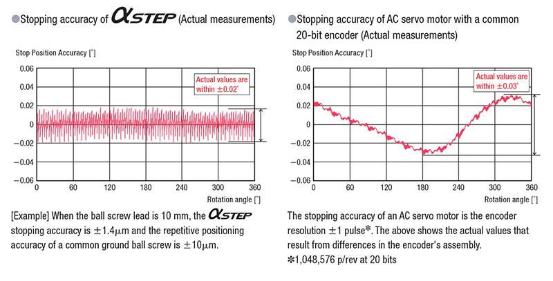
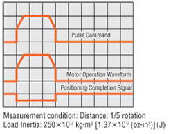
What is the Stopping Accuracy of αSTEP?
The stopping accuracy of a typical αSTEP is ±0.05° (under no load), which is equivalent to that of servo motors. The graphs below show the actual measured stopping accuracies when an αSTEP and an AC servo motor were rotated once.
Pulse Input Type
High Reliability with Closed Loop Control
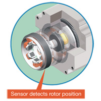
The αSTEP AR Series stepper motor uses Oriental Motor's closed loop control to maintain positioning operation even during abrupt load fluctuations and accelerations. The rotor position detection sensor monitors the rotation. When an overload condition is detected, the αSTEP AR Series will instantaneously regain control using the closed loop mode. When an overload condition continues, the αSTEP AR Series will output an alarm signal, thereby providing reliability equal to that of a servo motor.
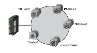
A Single Driver to Support a Variety of Motors
The driver is equipped with an automatic recognition function, which recognizes the attached motor. Various types of motors, such as the standard type and the geared type, can be attached to a single driver. Therefore, there is no need to change the driver to match the motor to be attached. Maintenance is easier.
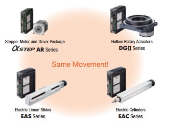
Actuators Equipped with AR Series
All of the products equipped with the αSTEP AR series feature standardized controllability.
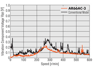
Low Vibration
In addition to the microstep drive system, the αSTEP AR Series also uses the smooth drive function to allow for smoother motion. The smooth drive function automatically implements microstep drive based on the same travel amount and speed used in the full-step mode, without changing the pulse input settings.
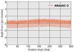
Improved Angle Accuracy
The αSTEP AR Series uses improved current control technology to improve the stop position accuracy of the stepper motor. The result is greater position accuracy.
AR66AC-3: ±3 arc minutes
Conventional Model: ±5 arc minutes
Performance of a Stepper Motor
The αSTEP AR Series maintains all of the benefits of a stepper motor.
High Response
The stepper motor operates synchronously with pulse commands to achieve high response. There's no delay in operation following a pulse command.
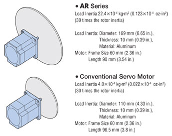
Capable of Driving Large Inertia Loads
Compared to a servo motor of the same frame size, a larger inertial load can be driven regardless of speed conditions.
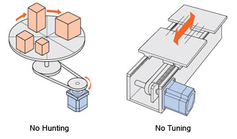
No Hunting / No Tuning
Because it uses a stepper motor, the αSTEP AR Series does not hunt when stopped. Accordingly, the αSTEP AR Series is ideal for applications where the equipment uses a belt-drive mechanism or otherwise has low rigidity and you don't want it to vibrate when stopping.
With the αSTEP AR Series, you can perform positioning quickly after a load change, etc., without adjusting any gains.
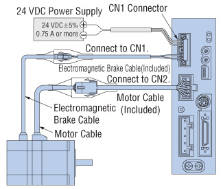
Automatically Controlled Electromagnetic Brake
A separate circuit is not needed to control the electromagnetic brake. The electromagnetic brake is released when the motor is excited (=current ON input is turned ON), and activated to hold the load in position when the excitation is cut off (=the current ON input is turned OFF).
Major Safety Standards
The αSTEP AR Series is recognized by the UL/CSA Standards and bears the CE Mark as proof of conformance to the Low Voltage and EMC Directives.
Complying with the Semiconductor Manufacturing Facility Standard "SEMI F47"
The αSTEP AR Series complies with the SEMI Standard on power supply voltage drop, and accordingly this motor can be used effectively in semiconductor manufacturing apparatuses. The customer is advised to always evaluate the stepper motor on the actual equipment.
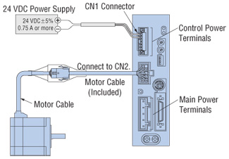
Separation of Main Power and Control Power
The control power-input terminals are provided separately from the main power terminals. This means that even when the main power is cut off due to an emergency stop, etc., you can still detect current position and check information on each alarm, etc., as long as the power (24 VDC) is supplied to the control power-input terminals.
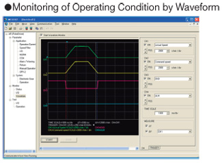
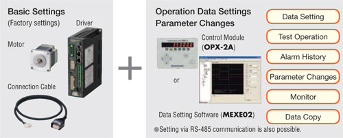
Extended Functions
You can combine a control module (OPX-2A) (sold separately) or data setting software* (MEXE02) both to change parameters, add functions and perform various monitoring operations according to the needs of your system.
- Parameter Setting Adjustments
- Monitoring
- Return Operation
- Push-Motion Operation
*Cable for connection to PC required for MEXE02 data setting software (sold separately**- see Accessories).
**One FREE CC05IF-USB communications cable is available per customer, contact Technical Support for more information.
Return Operation
Two return operation functions are available: return to electrical home operation and automatic return operation. With these options, you can easily set up your system to return home when the main power has been cut off due to an emergency stop, etc., or the motor excitation has been turned off.
While the main power is cut off, the control power (24 VDC) must be supplied in order to maintain positioning.
Return to Electrical Home Operation
An operation in which the motor returns to the "position it had assumed when the power was turned on (=electrical home)" or "location set as the electrical home".
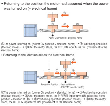
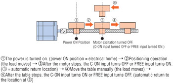
Automatic Return Operation
An operation in which the motor returns to the "position at which motor excitation was turned off (= the C-ON input turned OFF or FREE input turned ON)."
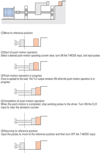
Push-Motion Operation
You can input pulses to perform push-motion operation where the load continuously has force applied to it. The amount of force (motor output torque) is set by the push-motion operating current value. Using a control module (OPX-2A) or data setting software (MEXE02) (both sold separately), change the applicable parameter to "Push-motion operation" turn the T-MODE input ON, and input pulses. The motor will start the push-motion operation.
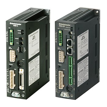
Stored Data (Network) Type Driver with Built-in Controller
Built-in Controller (Stored Data Type) Driver
A built-in pulse generator allows the motor to be driven by connection to a PLC or other devices with connection through a Factory Automation (FA) network via I/O control. Modbus (RTU) control, or a network converter.
The burden on the programmable PLC is reduced because the information necessary for motor operations is built into the driver. This simplifies the system configuration for multi-axis control. Set with control module (sold separately), data setting software or RS-485 communication.
Equipped with an Interface that Connects to Various Master Control Systems
FLEX is the generic name for products that are used for Factory Automation (FA) network control via I/O control, Modbus (RTU) control, or a network converter.
FLEX products enable easy connection, easy control, and reduce the complexity of system configuration.
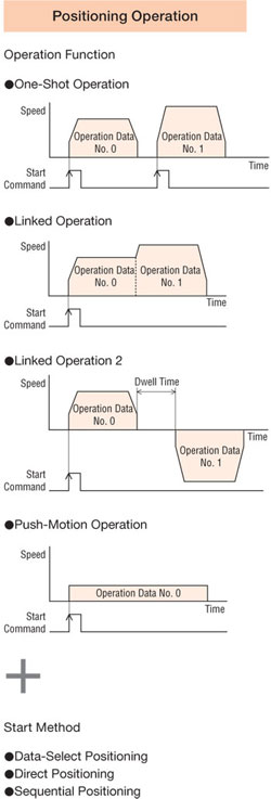
Operation Type
With built-in controller packages, the motor's operating speed and traveling amount are set with operating data and operations performed based on the selected operating data. The operation type is 4-pattern.
Item |
Content |
||
Common |
Control Method |
Up to 31 drivers can be connected to the master controller |
|
I/O Control |
|||
RS-485 communication |
Network Converter Connection |
||
Modbus RTU Protocol Connection |
|||
Position Command Input |
Set with operating data number |
||
Speed Command Input |
Set with operating data number |
||
Acceleration / Deceleration Command Input |
Set with operating data number or parameters. |
||
Acceleration / Deceleration Control |
Velocity filter, moving average filter |
||
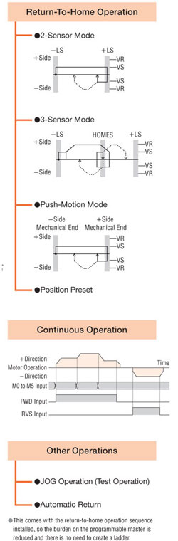
Return-To-Home Operation |
Return-To-Home Method |
2-sensor mode |
This is the return-to-home operation using limit sensors (+LS, -LS). |
3-sensor mode |
This is the return-to-home operation using limit sensors and HOME sensor. |
||
Pushing mode*1 |
This is the return-to-home operation for pushing to the mechanical end of a linear slide, etc. |
||
Position preset |
This function allows a home position to be confirmed by inputting P-PRESET using an arbitrary position. |
||
An arbitrary value can be set for the home position. |
|||
Positioning Operation |
Number of Positioning Points |
64 points (No. 0 ~ 63) |
|
Operation Mode |
Incremental mode (Relative positioning) |
||
Absolute mode (Absolute positioning) |
|||
Operation Functions |
One-shot operation |
This is a PTP (Point to Point) positioning operation. |
|
Linked operation |
This is a multistep speed-change positioning operation linked to operating data. |
||
Linked operation 2 |
This is a positioning operation with timer linked to operating data. |
||
Push-motion operation*1 |
Continuous pressurizing position operations are performed with respect to load. The operating speed is maximum 30 r/min] with the motor shaft. |
||
Starting Methods |
Operating data selection mode |
The positioning operation starts when START is input after M0 ~ M5 has been selected. |
|
Direct mode (direct positioning) |
The positioning operation starts with the operating data number that was set with the parameters when MS0 ~ MS5 has been input. |
||
Sequential mode (sequential positioning) |
The positioning operation starts in order from operating data No. 0 every time SSTART is input. |
||
Continuous Operation |
Number of Speed Points |
64 points (No. 0 ~ 63) |
|
Speed-Change Method |
This switches the operating data number. |
||
Other Operations |
JOG Operation |
+JOG or -JOG is input, and regular feeding is performed. |
|
Automatic Return Operation |
This automatically returns to the original stopped position when the motor has become misaligned due to an external force during non-excitation. |
||
Control Mode*2 |
The normal mode or the current control mode can be selected. |
||
*1 Do not perform push-motion operations with geared types. Doing so will damage the motor and gearhead.
*2 Use of the normal mode is recommended unless less heat generation and less noise is required.
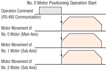
Group Sending Function (via RS-485 communication or Network Converter)
Groups can be configured with multiple axes connected via RS-485 communication, and commands sent to each group. Multi-axis simultaneous starting and identical operations are also possible.
Teaching Function
Teaching can be done using the control module OPX-2A (sold separately) or data setting software MEXE02. The table is moved to the desired position, and the position data at that time stored as the positioning data.

High Reliability with Closed Loop Control
The αSTEP AR Series uses Oriental Motor's closed loop control to maintain positioning operation even during abrupt load fluctuations and accelerations. The rotor position detection sensor monitors the rotation. When an overload condition is detected, the αSTEP AR Series will instantaneously regain control using the closed loop mode. When an overload condition continues, the αSTEP AR Series will output an alarm signal, thereby providing reliability equal to that of a servo motor.
A Single Driver to Support a Variety of Motors
The driver is equipped with an automatic recognition function, which recognizes the attached motor. Various types of motors, such as the standard type and the geared type, can be attached to a single driver. Therefore, there is no need to change the driver to match the motor to be attached. Maintenance is easier.
Actuators Equipped with AR Series
All of the products equipped with the αSTEP AR series feature standardized controllability.
Low Vibration
In addition to the microstep drive system, the αSTEP AR Series also uses the smooth drive function to allow for smoother motion. The smooth drive function automatically implements microstep drive based on the same travel amount and speed used in the full-step mode, without changing the pulse input settings.
Improved Angle Accuracy
The αSTEP AR Series uses improved current control technology to improve the stop position accuracy of the stepper motor. The result is greater position accuracy.
AR66AC-3: ±3 arc minutes
Conventional Model: ±5 arc minutes
Performance of a Stepper Motor
The αSTEP AR Series maintains all of the benefits of a stepper motor.
High Response
The stepper motor operates synchronously with pulse commands to achieve high response. There's no delay in operation following a pulse command.
Capable of Driving Large Inertia Loads
Compared to a servo motor of the same frame size, a larger inertial load can be driven regardless of speed conditions.
No Hunting / No Tuning
Because it uses a stepper motor, the αSTEP AR Series does not hunt when stopped. Accordingly, the αSTEP AR Series is ideal for applications where the equipment uses a belt-drive mechanism or otherwise has low rigidity and you don't want it to vibrate when stopping.
With the αSTEP AR Series, you can perform positioning quickly after a load change, etc., without adjusting any gains.
Automatically Controlled Electromagnetic Brake
A separate circuit is not needed to control the electromagnetic brake. The electromagnetic brake is released when the motor is excited (=current ON input is turned ON), and activated to hold the load in position when the excitation is cut off (=the current ON input is turned OFF).
Major Safety Standards
The αSTEP AR Series is recognized by the UL/CSA Standards and bears the CE Mark as proof of conformance to the Low Voltage and EMC Directives.
Complying with the Semiconductor Manufacturing Facility Standard "SEMI F47"
The αSTEP AR Series complies with the SEMI Standard on power supply voltage drop, and accordingly this motor can be used effectively in semiconductor manufacturing apparatuses. The customer is advised to always evaluate the stepper motor on the actual equipment.
Separation of Main Power and Control Power
The control power-input terminals are provided separately from the main power terminals. This means that even when the main power is cut off due to an emergency stop, etc., you can still detect current position and check information on each alarm, etc., as long as the power (24 VDC) is supplied to the control power-input terminals.
Extended Functions
You can combine a control module (OPX-2A) (sold separately) or data setting software* (MEXE02) both to change parameters, add functions and perform various monitoring operations according to the needs of your system.
- Parameter Setting Adjustments
- Monitoring
- Return Operation
- Push-Motion Operation
*Cable for connection to PC required for MEXE02 data setting software (sold separately**- see Accessories).
**One FREE CC05IF-USB communications cable is available per customer, contact Technical Support for more information.
Return Operation
Two return operation functions are available: return to electrical home operation and automatic return operation. With these options, you can easily set up your system to return home when the main power has been cut off due to an emergency stop, etc., or the motor excitation has been turned off.
While the main power is cut off, the control power (24 VDC) must be supplied in order to maintain positioning.
Return to Electrical Home Operation
An operation in which the motor returns to the "position it had assumed when the power was turned on (=electrical home)" or "location set as the electrical home".
Automatic Return Operation
An operation in which the motor returns to the "position at which motor excitation was turned off (= the C-ON input turned OFF or FREE input turned ON)."
Push-Motion Operation
You can input pulses to perform push-motion operation where the load continuously has force applied to it. The amount of force (motor output torque) is set by the push-motion operating current value. Using a control module (OPX-2A) or data setting software (MEXE02) (both sold separately), change the applicable parameter to "Push-motion operation" turn the T-MODE input ON, and input pulses. The motor will start the push-motion operation.
AR Series Closed Loop Stepper Motors
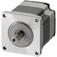
The αSTEP AR Series offer high efficiency, low vibration, continuous operation with the security of closed loop performance without hunting or gain tuning. Available with a built-in controller or pulse input driver, the system substantially reduces heat generation from the stepper motor through the use of high-efficiency technology. The αSTEP AR Series also achieves up to 40% less power consumption, improved angle accuracy and is capable of driving large inertia loads. For use with αSTEP AR Series Drivers.
- High-Efficiency, Continuous Operation
- Closed Loop Performance, No Hunting or Gain Tuning
- AC or DC Input Types
- Wide Range of Gear Types for Inertia Matching & Higher Torque
- Electromagnetic Brake Types
- αSTEP AR Series Driver Required*
Network Gateways
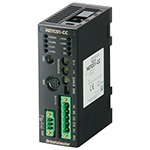
The communication protocol of the master controller, Factory Automation (FA) network, is converted to Oriental Motor's own RS-485 communication protocol. Connection to Oriental Motor's network compatible products is completed with one RS-485 communication cable.
- Compatible Networks:
CC-Link, MECHATROLINK-II, MECHATROLINK-III, EtherCat
*For use with Stored Data (Network) type
![]()
![]()
![]()
DIN Rail Mounting Plate
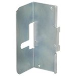
Use to mount the driver on DIN rail.
RS-485 Communication Cable
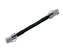
These cables are used to link drivers when a built-in controller type is being operated in a multi-drop manner.
*For use with Stored Data (Network) type
Power Supply Cables
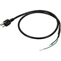
Power Supply cable for the AR Series.
Control Options - Control Module
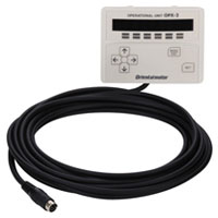
The internal driver parameter settings and data settings can be established and changed. They can also be used for speed and I/O monitoring, teaching, and so on.
Control Options - Support Software
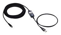
This communication cable is required for connecting to the computer on which the data setting software is installed.
Driver Cables
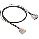
General-purpose multi-conductor cable which is convenient for connection between the driver and host controller.
*For use with Pulse Input Type driver.
Straight-Type
Item |
Applicable Connector |
Length |
CN5 (36 pins) |
3.3 ft. (1 m) |
|
6.6 ft. (2 m) |
Right-Angle Type
Item |
Applicable Connector |
Length |
CN5 (36 pins) |
3.3 ft. (1 m) |
|
6.6 ft. (2 m) |
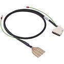
Terminal Block Connector
These are conversion units that can connect a driver to a programmable controller or a sensor using a terminal block.
*For use with Pulse Input Type driver.
Item |
Applicable Connector |
Length |
CN5 (36 pins) |
3.3 ft. (1 m) |
Regeneration Unit
During vertical driver (gravitational operation) or suddent start/stop in high inertia, an external force causes the motor to rotate and funciton as a power generator. When the regenerative power exceeds the driver's regenerative power absorption capacity, it may cause damage to the motor. In such a case, the regeneration unit is connected to the driver to convert regenerative energy into thermal energy for dissipation.
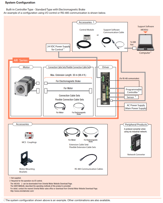
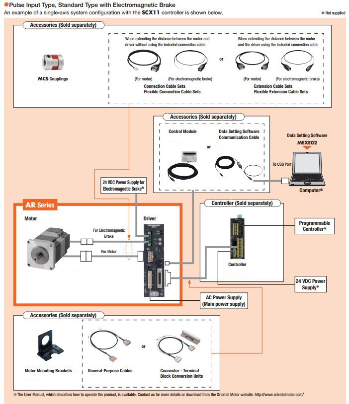
System Configuration
Motor & Driver Combinations
AC Input
|
Built-in Controller (Network) |
Pulse Input |
||||||
Gear |
Rear |
Size |
Motor P/N |
Driver P/N |
Rear |
Size |
Motor P/N |
Driver P/N |
Round |
Single |
46 |
ARM46AC |
ARD-♢D2 |
Single |
46 |
ARM46AC |
ARD-♢ |
66 |
ARM66AC |
66 |
ARM66AC |
|||||
69 |
ARM69AC |
69 |
ARM69AC |
|||||
98 |
ARM98AC |
98 |
ARM98AC |
|||||
911 |
ARM911AC |
911 |
ARM911AC |
|||||
Double |
46 |
ARM46BC |
Double |
46 |
ARM46BC |
|||
66 |
ARM66BC |
66 |
ARM66BC |
|||||
69 |
ARM69BC |
69 |
ARM69BC |
|||||
98 |
ARM98BC |
98 |
ARM98BC |
|||||
911 |
ARM911BC |
911 |
ARM911BC |
|||||
Electromagnetic |
46 |
ARM46MC |
Electromagnetic |
46 |
ARM46MC |
|||
66 |
ARM66MC |
66 |
ARM66MC |
|||||
69 |
ARM69MC |
69 |
ARM69MC |
|||||
98 |
ARM98MC |
98 |
ARM98MC |
|||||
|
Single |
46 |
ARM46AC |
ARD-S* |
||||
66 |
ARM66AC |
|||||||
69 |
ARM69AC |
|||||||
98 |
ARM98AC |
|||||||
911 |
ARM911AC |
|||||||
Double |
46 |
ARM46BC |
||||||
66 |
ARM66BC |
|||||||
69 |
ARM69BC |
|||||||
98 |
ARM98BC |
|||||||
911 |
ARM911BC |
|||||||
Electromagnetic |
46 |
ARM46MC |
||||||
66 |
ARM66MC |
|||||||
69 |
ARM69MC |
|||||||
98 |
ARM98MC |
|||||||
TH Geared |
Single |
46 |
ARM46AC-T☐ |
ARD-♢D2 |
Single |
46 |
ARM46AC-T☐ |
ARD-♢ |
66 |
ARM66AC-T☐ |
66 |
ARM66AC-T☐ |
|||||
98 |
ARM98AC-T☐ |
98 |
ARM98AC-T☐ |
|||||
Electromagnetic |
46 |
ARM46MC-T☐ |
Electromagnetic |
46 |
ARM46MC-T☐ |
|||
66 |
ARM66MC-T☐ |
66 |
ARM66MC-T☐ |
|||||
98 |
ARM98MC-T☐ |
98 |
ARM98MC-T☐ |
|||||
|
Single |
46 |
ARM46AC-T☐ |
ARD-S* |
||||
66 |
ARM66AC-T☐ |
|||||||
98 |
ARM98AC-T☐ |
|||||||
Electromagnetic |
46 |
ARM46MC-T☐ |
||||||
66 |
ARM66MC-T☐ |
|||||||
98 |
ARM98MC-T☐ |
|||||||
PS Geared |
Single |
46 |
ARM46AC-PS☐ |
ARD-♢D2 |
Single |
46 |
ARM46AC-PS☐ |
ARD-♢ |
66 |
ARM66AC-PS☐ |
66 |
ARM66AC-PS☐ |
|||||
98 |
ARM98AC-PS☐ |
98 |
ARM98AC-PS☐ |
|||||
Electromagnetic |
46 |
ARM46MC-PS☐ |
Electromagnetic |
46 |
ARM46MC-PS☐ |
|||
66 |
ARM66MC-PS☐ |
66 |
ARM66MC-PS☐ |
|||||
98 |
ARM98MC-PS☐ |
98 |
ARM98MC-PS☐ |
|||||
|
Single |
46 |
ARM46AC-PS☐ |
ARD-S* |
||||
66 |
ARM66AC-PS☐ |
|||||||
98 |
ARM98AC-PS☐ |
|||||||
Electromagnetic |
46 |
ARM46MC-PS☐ |
||||||
66 |
ARM66MC-PS☐ |
|||||||
98 |
ARM98MC-PS☐ |
|||||||
PN Geared |
Single |
46 |
ARM46AC-N☐ |
ARD-♢D2 |
Single |
46 |
ARM46AC-N☐ |
ARD-♢ |
66 |
ARM66AC-N☐ |
66 |
ARM66AC-N☐ |
|||||
98 |
ARM98AC-N☐ |
98 |
ARM98AC-N☐ |
|||||
Electromagnetic |
46 |
ARM46MC-N☐ |
Electromagnetic |
46 |
ARM46MC-N☐ |
|||
66 |
ARM66MC-N☐ |
66 |
ARM66MC-N☐ |
|||||
98 |
ARM98MC-N☐ |
98 |
ARM98MC-N☐ |
|||||
|
Single |
46 |
ARM46AC-N☐ |
ARD-S* |
||||
66 |
ARM66AC-N☐ |
|||||||
98 |
ARM98AC-N☐ |
|||||||
Electromagnetic |
46 |
ARM46MC-N☐ |
||||||
66 |
ARM66MC-N☐ |
|||||||
98 |
ARM98MC-N☐ |
|||||||
Harmonic |
Single |
46 |
ARM46AC-H☐ |
ARD-♢D2 |
Single |
46 |
ARM46AC-H☐ |
ARD-♢ |
66 |
ARM66AC-H☐ |
66 |
ARM66AC-H☐ |
|||||
98 |
ARM98AC-H☐ |
98 |
ARM98AC-H☐ |
|||||
Electromagnetic |
46 |
ARM46MC-H☐ |
Electromagnetic |
46 |
ARM46MC-H☐ |
|||
66 |
ARM66MC-H☐ |
66 |
ARM66MC-H☐ |
|||||
98 |
ARM98MC-H☐ |
98 |
ARM98MC-H☐ |
|||||
|
Single |
46 |
ARM46AC-H☐ |
ARD-S* |
||||
66 |
ARM66AC-H☐ |
|||||||
98 |
ARM98AC-H☐ |
|||||||
Electromagnetic |
46 |
ARM46MC-H☐ |
||||||
66 |
ARM66MC-H☐ |
|||||||
98 |
ARM98MC-H☐ |
|||||||
♢ = A (Single 100-120 VAC) / C (Single 200-240VAC)
*S = Three Phase 200-240V
☐ = Gear Ratio
CAD / Manual Search
To locate product CAD and Operator Manuals please search using the product Item Number.
Downloads
Videos
Technical Articles
Reference
Videos
Closed Loop Stepper Motors
Cooling Fans