Linear Actuators > Linear Cylinders
Linear Actuators - Electric Linear Cylinders
αSTEP EAC Closed Loop AZ Series Absolute Encoder Electric Linear Cylinders / Linear Actuators
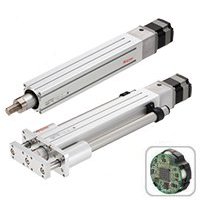
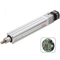
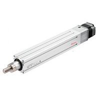
The αSTEP EAC Series electric linear actuators featuring AZ Series with absolute encoder stepper motor and driver are quick and responsive and incorporate a ball screw design, offering high performance from low speed to high speed or with light loads or heavy loads, regardless of demanding operating conditions. Available in a straight type or reversed motor type and with a shaft guide and cover version also available, saves design time and parts. All EAC Series are available with an electromechanical brake ideal for vertical operations.
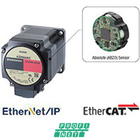
- Equipped with battery-free absolute encoder
- Positioning information can be known without a sensor
- High reliability using closed loop control
- Reduced motor heat and reduced energy consumption through high efficiency design
- Requires AZ Series Driver (sold separately)
Linear Actuator Comparison
Product Series |
||
|
|
|
Features |
Closed Loop, Absolute Mechanical Encoder |
Closed Loop, High-Efficiency |
Stroke Lengths |
50 ~ 300 mm |
50 ~ 300 mm |
Driver Required |
AZ Series |
AR Series |
Driver Input Power |
AC or DC Input |
AC or DC Input |
Available Options |
Reversed Motor Type Guide Type with Cover Electromagnetic Brake |
Reversed Motor Type Guide Type with Cover Electromagnetic Brake |
Max. Speed |
300 or 600 mm/s |
300 or 600 mm/s |
Max. Push Force |
~500 N |
~400 N |
Max. Thrust Force |
~400 N |
~400 N |
Learn More |
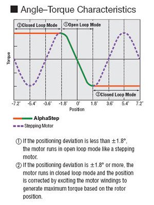
αSTEP Hybrid Control System
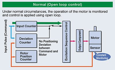
αSTEP products are stepper motor based hybrid motors with a unique hybrid control system combining the benefits of "open loop control" and "closed loop control".
The position of the motor is always monitored, and then the driver automatically switches between 2 types of control depending on the situation.
Normally Operates in Open Loop Control for the Same Ease of Use as a Stepper Motor
High Response
By utilizing the high responsiveness of the stepper motor, moving a short distance for a short time is possible. The motors can execute commands without lag.
Holding the Stop Position without Hunting
During positioning, the motor stops with its own holding force without hunting. Because of this, it is ideal for applications where the low rigidity of the mechanism requires absence of vibration upon stopping.
Tuning-Free
Because it is normally operated with open loop control, positioning is still possible without gain adjustment even when the load fluctuates due to the use of a belt mechanism, cam or chain drive, etc.
Switches to Closed Loop Control during Overload for More Reliable Operation like a Servo Motor
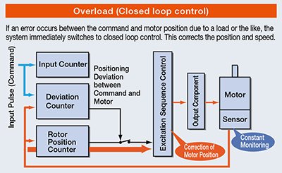
Continues Operation Even with Sudden Load Fluctuation and Sudden Acceleration
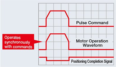
It operates synchronously with commands using open loop control during normal conditions. In an overload condition, it switches immediately to closed loop control to correct the position.
Alarm Signal Output in Case of Abnormality
If an overload is applied continuously, an alarm signal is output. When the positioning is complete, and END signal is output. This ensures the same level of reliability as a servo motor.
αSTEP AZ Series Product Family
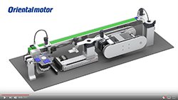
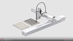
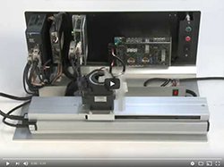
Linear Actuator Videos
Linear Actuator Technical Articles